
Offset determination for measurement system matching

a measurement system and offset determination technology, applied in the field of measurement systems, can solve the problems of reducing throughput, difficult to separate the inherent noise associated with the measurement system data from the real process excursion, and inaccurate offsets for the measurement system

Inactive Publication Date: 2008-01-08
IBM CORP
View PDF11 Cites 5 Cited by
  • Summary
  • Abstract
  • Description
  • Claims
  • Application Information

AI Technical Summary

Benefits of technology

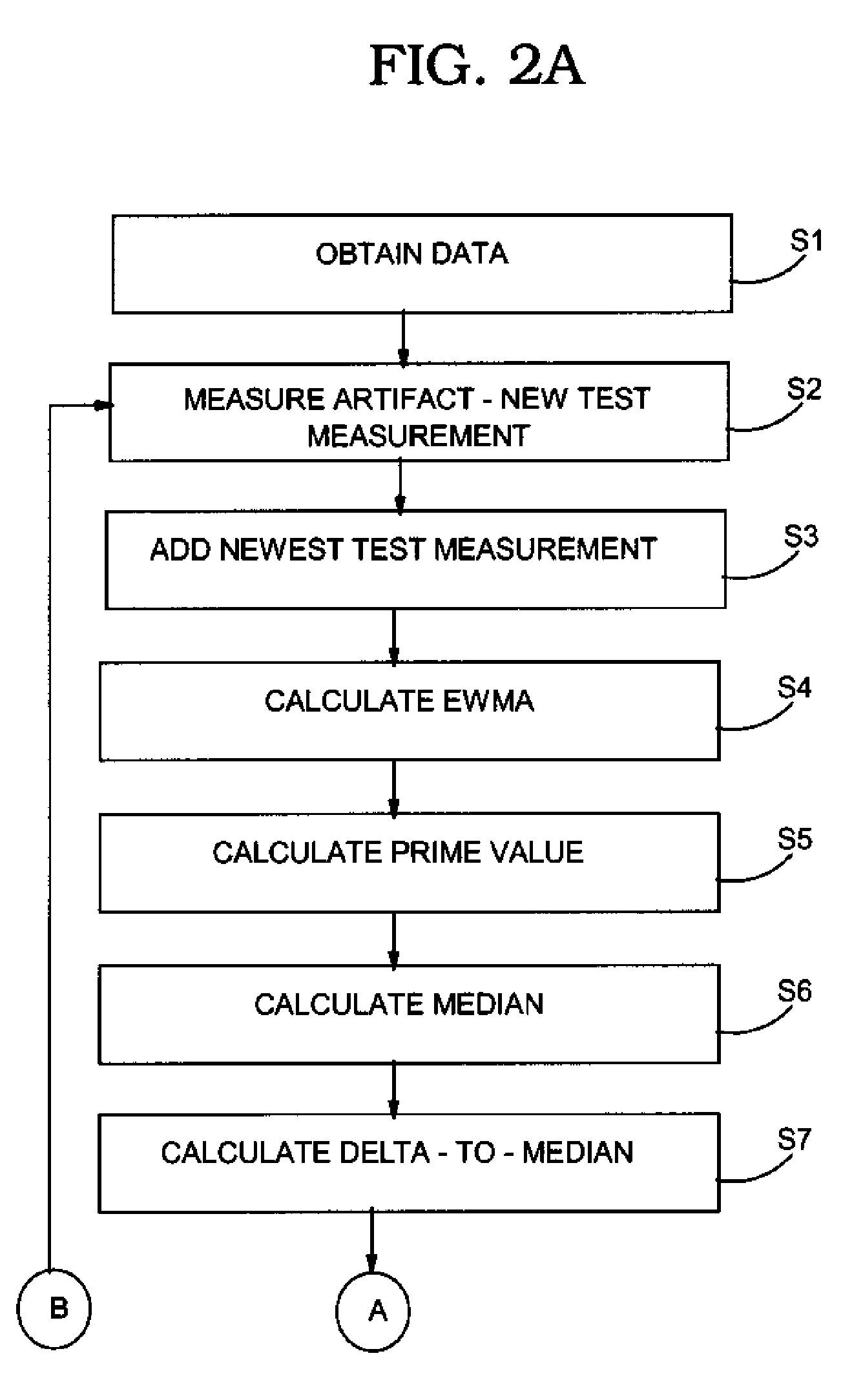
The patent describes a method for determining offsets for multiple measurement systems. The method involves measuring an artifact on a monitor wafer for each system and adding the measurements to a set. An exponentially weighted moving average is then calculated for each system, and the average is used to determine a new offset for each system. This new offset is then applied to product measurements to correct any tool matching issues. The technical effect of this invention is to provide a more accurate and reliable method for matching multiple measurement systems.

Problems solved by technology

There are a number of challenges currently facing the industry relative to measurement systems.
One challenge is correctly assessing the measurement potential of a measurement system and matching the measurement system to other measurement systems.
Unfortunately, it is oftentimes difficult to separate the inherent noise associated with the measurement systems data from real process excursions with a high confidence level.
As a result, offsets for a measurement system are oftentimes inaccurate.
Even though this approach results in more uniform measurements, this solution is not desirable because it reduces throughput and increases the risk to a production line by the use of a limited number of measurement systems to support a potentially critical process.
Another challenge relative to measurement system matching is addressing changes in artifacts on monitor wafers over time, which frustrates the ability to match measurement systems.
For example, in the semiconductor industry the thickness of a thin-gate oxide film on the surface of a silicon wafer is known to change over time due to environmental conditions.
As a result, measurements of an artifact made of that material changes over time, and creates inaccuracies for static measurement system offsets.

Method used


Image

  • Offset determination for measurement system matching
  • Offset determination for measurement system matching
  • Offset determination for measurement system matching

Examples


Embodiment Construction

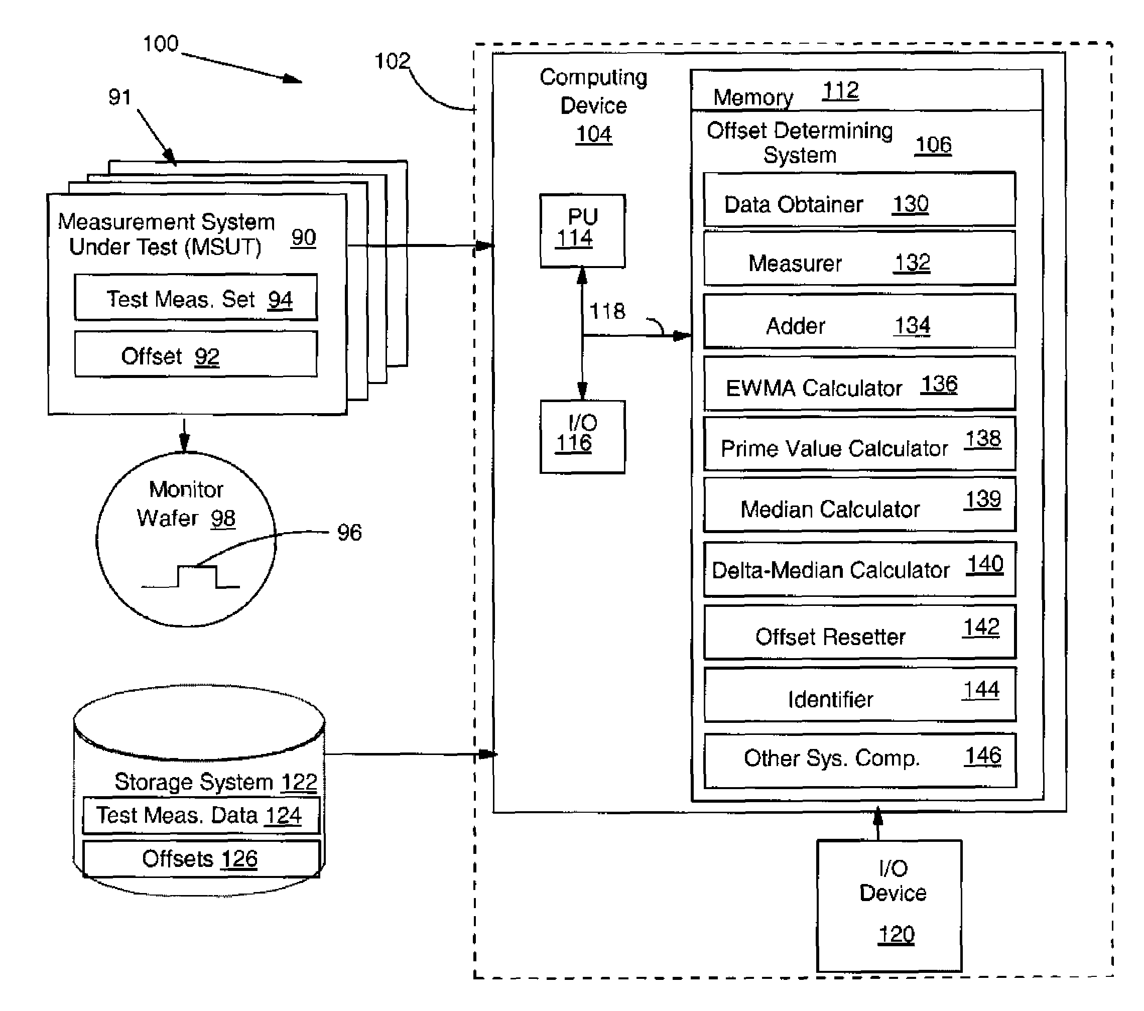
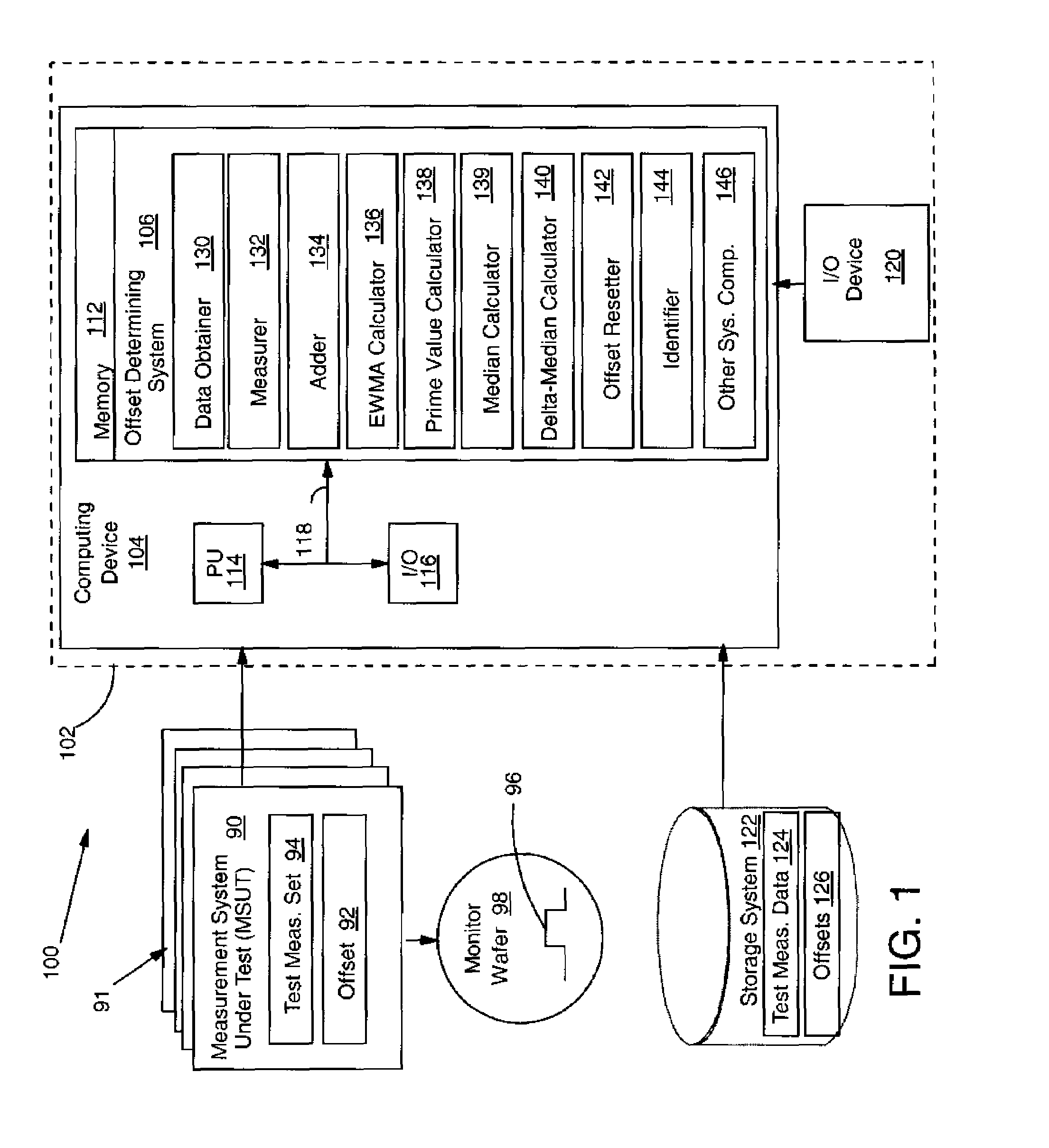
[0021]Turning to the drawings, FIG. 1 shows an illustrative environment 100 for determining an offset for each measurement system 90 with a plurality of measurement systems 91. A particular measurement system 90 under evaluation is referred to herein as a measurement system under test (MSUT) 90. Each measurement system 90 may include one or more metrology tools such as a scanning electron microscope (SEM), atomic force microscope (AFM), etc. It should be recognized, however, that the teachings of the invention are applicable to any type of measurement system and plurality of different types of measurement systems. As shown, each measurement system 90 may include an offset 92, which establishes a correction value for each measurement the particular measurement system makes, and a set of test measurements 94 of an artifact 96 of a monitor wafer 98. As will be described below, each measurement system 90 measures an artifact 96 on a monitor wafer 98 to obtain a test measurement. As used...


PUM


Abstract

Dynamic offset determination for each of a plurality of measurement systems for matching the systems is disclosed. One embodiment uses an artifact which is periodically run across the measurement system to be matched. Inputs for each run include the current offsets and historical data for the entire fleet and the new test measurement for the current measurement system under test. Evaluation based on exponentially weighted moving average and median calculation techniques may result in a new, reset offset for one or more measurement systems. The reset offset(s) is then applied to product measurements to nullify any tool matching issues.

Description

BACKGROUND OF THE INVENTION[0001]1. Technical Field[0002]The invention relates generally to measurement systems, and more particularly, to a method, system and program product to determine a dynamic offset for measurement system matching.[0003]2. Background Art[0004]Efficient semiconductor manufacturing requires highly precise and accurate measurement systems, i.e., metrology instruments. In particular, a measurement system is required to achieve small tolerances to achieve better quality products and fewer rejections in the manufacturing process. There are a number of challenges currently facing the industry relative to measurement systems. One challenge is correctly assessing the measurement potential of a measurement system and matching the measurement system to other measurement systems. Conventionally, when a stable artifact (NIST traceable) is not available, a plurality of measurement systems are matched by having each system test measuring a particular artifact on a monitor w...

Claims


Application Information

Patent Timeline
Patent Type & Authority Patents(United States)
IPC IPC(8): G06F17/50G01R31/26G06F19/00
CPCG01D18/006G06Q20/102
Inventor BRENDLER, ANDREW C.CHIANESE, DANIELLE R.JANKOVSKY, SUSAN M.YOUNG, ROGER M.
Owner IBM CORP
Learn More