
Dynamic stabilization and control of an earthmoving machine

a technology of dynamic stabilization and control, applied in the field of machine control, can solve the problems of system general precision limitation, time-consuming and labor-intensive, and currently available satellite navigation systems introduce other constraints, and achieve the effect of ensuring dynamic stability of a machin

Active Publication Date: 2008-01-08
TOPCON POSITIONING SYST INC
View PDF18 Cites 80 Cited by
  • Summary
  • Abstract
  • Description
  • Claims
  • Application Information

AI Technical Summary

Benefits of technology

The system achieves dynamic stability at faster speeds, reducing GPS measurement errors and delays, thereby enhancing productivity and accuracy in grading operations.

Problems solved by technology

One disadvantage of this mode of operation is that it is time consuming and labor intensive.
One of the constraints of existing systems is that the use of lasers for machine control requires a line of sight between the rotating laser and the construction machine.
While satellite navigation systems are free from the maximum distance constraint, the currently available satellite navigation systems introduce other constraints.
For example, these systems generally have limited precision, especially when calculating vertical measurements.
Another problem with satellite navigation machine control systems is the delay introduced into the control loop.
Another problem with existing machine control systems is dynamic instability at relatively fast operation speeds.
More particularly, at fast (but not maximum) bulldozer speeds, the bulldozer and attached blade tend to oscillate, therefore resulting in inaccurate grading.

Method used


Image

  • Dynamic stabilization and control of an earthmoving machine
  • Dynamic stabilization and control of an earthmoving machine
  • Dynamic stabilization and control of an earthmoving machine

Examples


Embodiment Construction

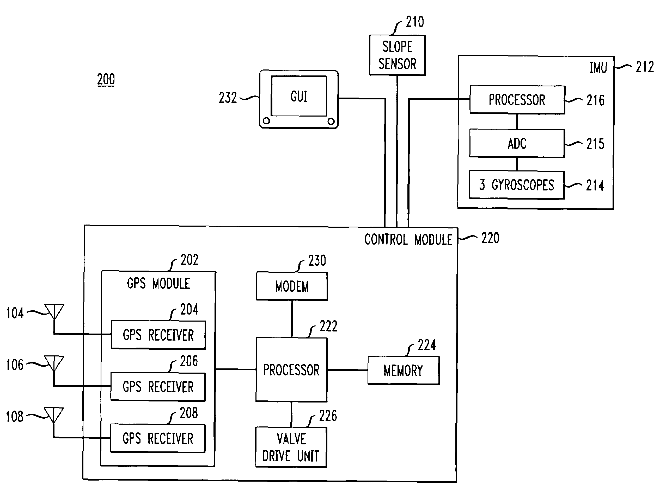
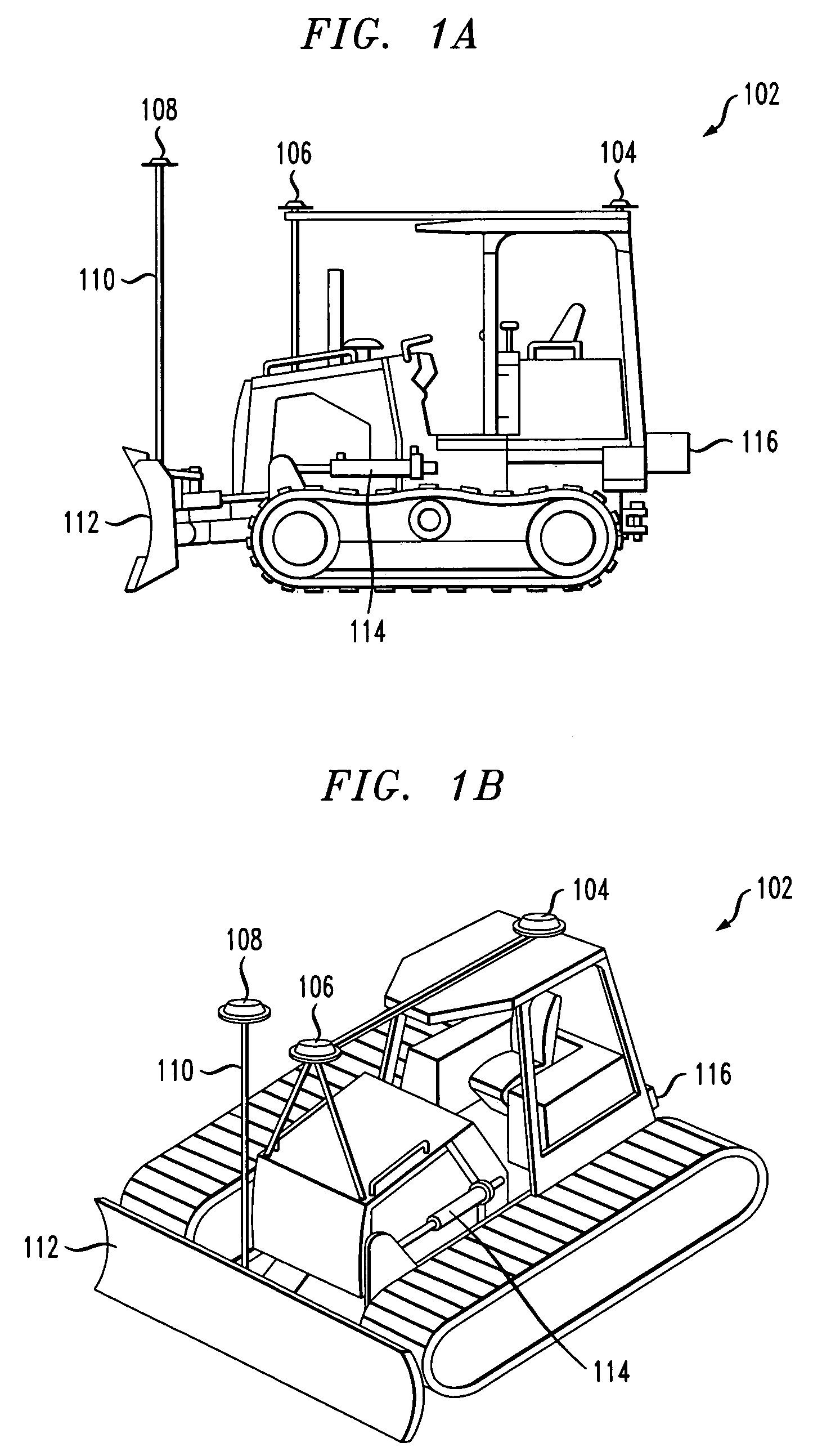
[0022]FIGS. 1A and 1B show a construction machine 102 in accordance with one embodiment of the present invention. FIG. 1A shows a side view of the construction machine 102 and FIG. 1B shows an elevated angular view of the construction machine 102. In the particular embodiment being described, the construction machine 102 is a bulldozer. However, as would be readily apparent to one skilled in the art, the principles of the present invention are applicable to other types of construction machines as well. Construction machine 102 has three satellite antennas 104, 106, 108 that are used to receive signals from Global Navigation Satellite Systems (GNSS). GNSS are well known and used to solve a wide variety of positioning / time related tasks. Two well known such systems are the Global Positioning System (GPS) of the United States and the GLObal NAvigation Satellite System (GLONASS) of Russia. For ease of reference, this description will generally refer to the GPS system, but it is to be un...


PUM


Abstract

An earthmoving machine including a control system is disclosed. The machine comprises first and second satellite navigation antennas mounted in a longitudinal direction on the earthmoving machine. A third satellite navigation antenna is mounted on a pole attached to an operational element of the earthmoving machine. In one embodiment, the earthmoving machine is a bulldozer and the operational element is a blade of the bulldozer. The machine further comprises a gravity reference sensor and a plurality of gyroscopes mounted on the machine. A computer processor generates control signals based on sensor data received from the various components. The disclosed system and method allows for dynamically stable operation of the earthmoving machine at relatively fast speeds without the development of unwanted oscillations.

Description

BACKGROUND OF THE INVENTION[0001]The present invention relates generally to machine control, and more particularly to the dynamic stabilization and control of a machine.[0002]Various types of machines, generally referred to herein as earthmoving machines, have been developed that alter the topology or geography of terrain. For example, a bulldozer with an attached and moveable cutting blade may be used in various earthmoving applications. During construction site preparation, a bulldozer may be used to level (or apply some predetermined slope) to the ground prior to construction of a building on the ground. Bulldozers are also useful in road and other construction applications. Of course, there are various uses for bulldozers and other earthmoving machines.[0003]Initially, the operation of bulldozers was performed by skilled operators in conjunction with a ground crew, for example a crew of grade correctors equipped with surveying instruments to ensure correct grading. This mode of ...

Claims


Application Information

Patent Timeline
Patent Type & Authority Patents(United States)
IPC IPC(8): G06F7/70
CPCE02F3/842E02F3/847E02F9/2045G05D1/0278G05D2201/0201
Inventor MATROSOV, IVAN
Owner TOPCON POSITIONING SYST INC
Learn More