Device for correcting thoracic spine positioning
a technology for thoracic spine and therapy device, which is applied in the field of therapeutic devices for the correction of thoracic spine positioning, can solve the problems of premature degeneration, poor posture, and number of physical ailments
- Summary
- Abstract
- Description
- Claims
- Application Information
AI Technical Summary
Benefits of technology
Problems solved by technology
Method used
Image
Examples
second embodiment
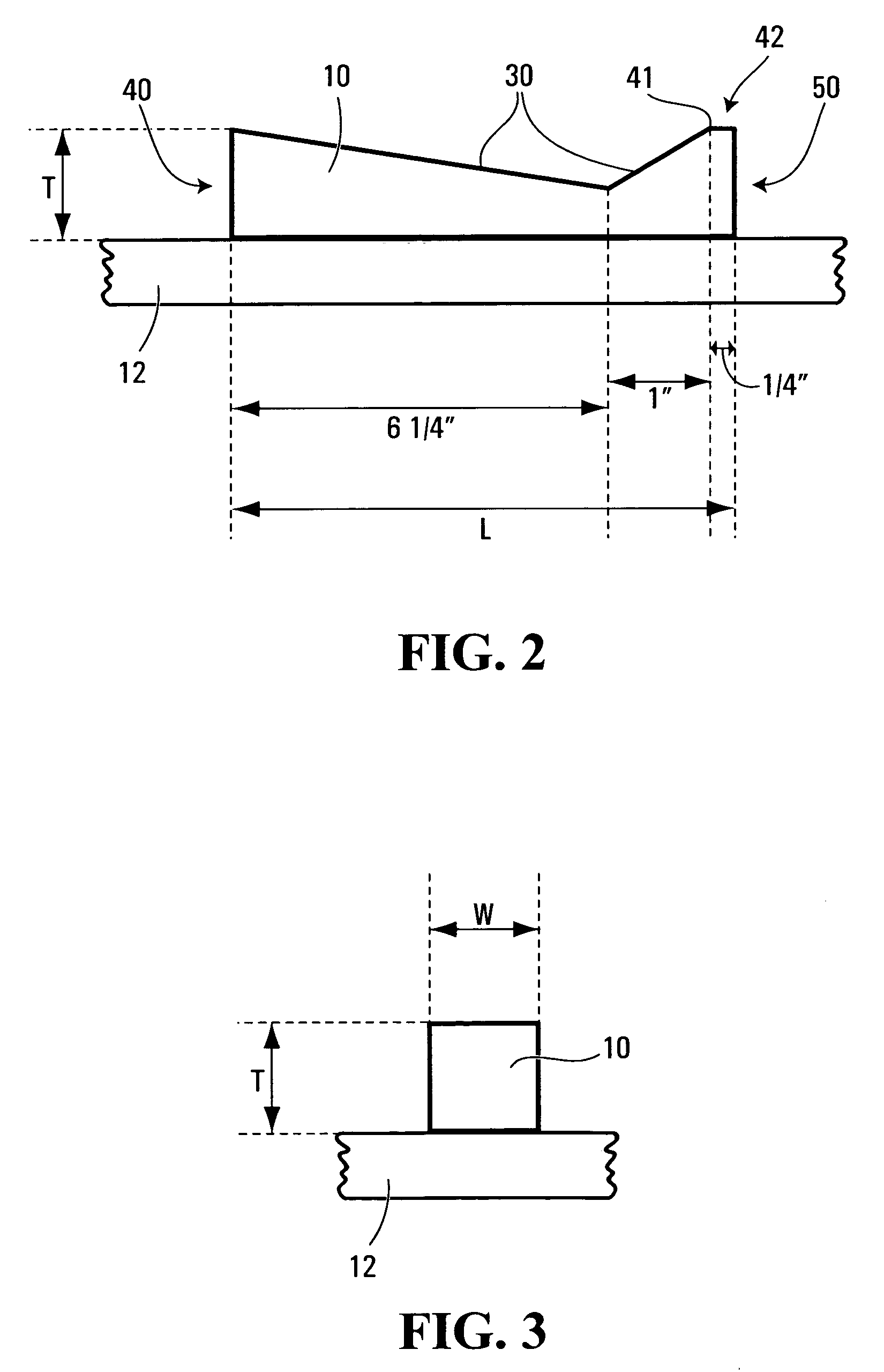
[0033]FIG. 2 depicts the present invention in which the upper surface (30) of the pad (10) has an asymmetrical V-shaped profile when viewed from the side that tapers downwardly from a top end (40) toward a bottom end (50) at about a 10 degree angle and also tapers downwardly from a point (41) near the bottom end (50) toward the top end (40) at about a 40 degree angle. In the case of a pad (10) that is 7½ inches long, the base of the asymmetrical V will be about 6¾ inches from the top end (40) and 1¼ inches from the bottom end (50). Because the point (41) from which the 40 degree angle tapering commences is removed from the bottom end (50), a protrusion (42) is created at the bottom end of pad (10).
[0034]In the case of the pad (10) of the second embodiment to the present invention illustrated in FIG. 2, the asymmetric V-shaped profile of the upper surface tends to force the upper thoracic spine into a more ergonomically anatomically sound position. The protrusion (42) found at the bo...
third embodiment
[0035]FIGS. 4 and 4(a) depict the present invention in which the upper surface (30) of the pad (10) has a longitudinal groove (55) extending from the top of the pad (40) to the bottom of the pad (50). The longitudinal groove (55) is equidistant between a right end of the pad (56) and a left end of the pad (57). When the pad (10) is positioned between the user's upper thoracic spine (11) and a substantially hard surface (12), the groove (55) is positioned to cradle the spinal processes of the vertebrae of the upper thoracic spine (11) when the user is applying pressure to the pad (10).
fourth embodiment
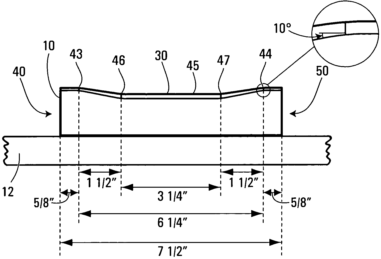
[0036]FIGS. 5 and 5(a) depict the present invention in which the upper surface (30) of the pad (10) has a symmetrical U-shaped profile when viewed from the side. A top end (40) of the pad (10) and a bottom end (50) of the pad (10) are of equal thickness. The top end (40) and the bottom end (50) are flat until a point near the top end (43) and a point near the bottom end (44) where the upper surface (30) begins tapering downwardly, at about a 10 degree angle, to a point from the top end where the tapering stops (46) and to a point from the bottom end where the tapering stops (47). Between the point from the top end where the tapering stops (46) and the point from the bottom end where the tapering stops (47) is a horizontal depression (45). In the case of a pad (10) that is 7½ inches long, the base of the symmetrical U will be about 6¼ inches wherein the downward tapering at about a 10 degree angle from the point near the top end (43) extends for about 1½ inches to a point from the to...
PUM
 Abstract
Description
Claims
Application Information
 - R&D
- Intellectual Property
- Life Sciences
- Materials
- Tech Scout
- Unparalleled Data Quality
- Higher Quality Content
- 60% Fewer Hallucinations
Browse by: Latest US Patents, China's latest patents, Technical Efficacy Thesaurus, Application Domain, Technology Topic, Popular Technical Reports.
© 2025 PatSnap. All rights reserved.Legal|Privacy policy|Modern Slavery Act Transparency Statement|Sitemap|About US| Contact US: help@patsnap.com


