Eureka AIR delivers breakthrough ideas for toughest innovation challenges, trusted by R&D personnel around the world.

Light source for generating an output signal having spaced apart frequencies

a light source and output signal technology, applied in the field of multi-wavelength light sources, can solve the problems of limiting the spread of output spectrum, rapid fall of intensity of spectral lines away from input (central) frequency, and unable to create a wide comb of frequencies, etc., and achieve the effect of different width

Inactive Publication Date: 2008-01-01
CELIGHT
View PDF16 Cites 14 Cited by
  • Summary
  • Abstract
  • Description
  • Claims
  • Application Information

AI Technical Summary

Benefits of technology

[0020]In yet another aspect of the invention, the crystal structure is engineered to have a periodicity higher than two, preferably comprising a plurality of units of domains eac

Problems solved by technology

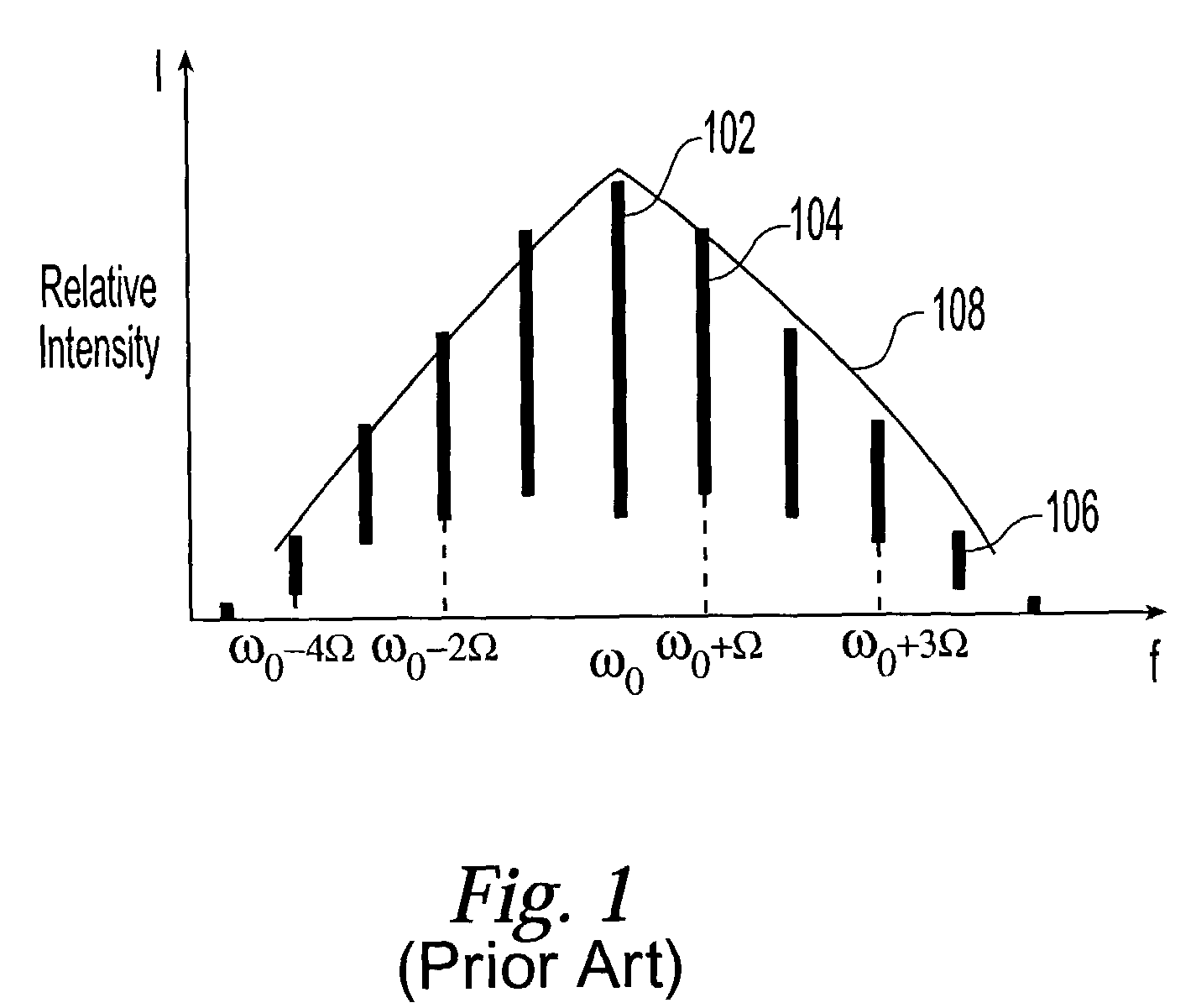
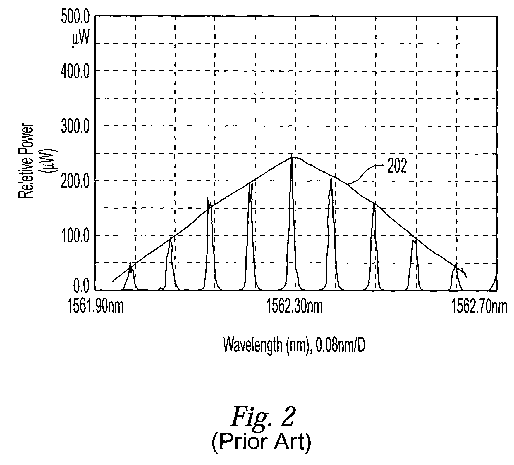
The rapid fall of the intensity for the spectral lines away from the input (central) frequency does not allow for the creation of a wide comb of frequencies having substantially same intensities, when just an EOM is used.
Further spreading of the output spectrum is limited mostly by waveguide dispersion that leads to a velocity mismatch between the applied RF signal and the optical wave.

Method used


Image

  • Light source for generating an output signal having spaced apart frequencies
  • Light source for generating an output signal having spaced apart frequencies
  • Light source for generating an output signal having spaced apart frequencies

Examples


Embodiment Construction

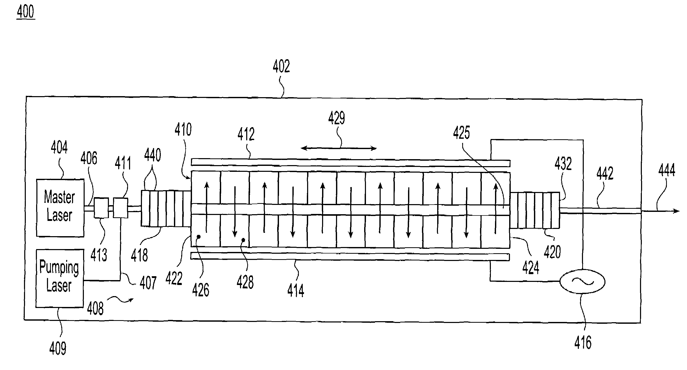
[0034]FIG. 4 shows a light source 400 in accordance with the present invention. The light source 400 may include a housing 402 and a number of individual components, such as a master laser 404, a pump laser 409, and an electro-optic waveguide modulator (EOM). In the embodiment of FIG. 4, the master laser 404 and pump laser 409 are shown to be enclosed within housing 402. It is understood, however, that these lasers may likewise be disposed outside the housing and optically coupled to other components by a suitable fiber, waveguide, or the like.

[0035]The master laser 404 generates a high-fidelity optical signal 406 preferably having a frequency f0 located within the C-band (191.6-195.9 THz). In a preferred embodiment, the master laser 404 may be obtained from Fiberspace, Inc, of Woodland Hills, Calif., with an optical phase-locked loop to produce highly stable laser radiation with long-term frequency stability within a range of 5 MHz.

[0036]The pump source 409 generates pump light hav...


PUM


Abstract

A multiple wavelength light source generates an output signal having a comb of accurately spaced apart frequencies with variable free spectral range in the C-band of optical fiber communication. The light source employs an electro-optical modulator (EOM) driven by a signal generator which modulates with EOM with multiple modulation frequencies to widen the output spectrum of signal. The EOM has a crystal provided with a waveguide. The waveguide may be doped with a rare-earth metal to impart gain properties to equalize the intensities of the comb. In one preferred embodiment, Er, Yt or other doping elements provide the gain property to waveguides. The crystal is also provided with periodically poled structure, and this may be engineered so as to form domains of unequal widths to improve the efficiency of modulation. The output signal from the light source may be split and presented to a bank of filters to create a multiple signals, each signal having one of the spaced apart frequencies. The output signals may be used as channels to be modulated by data and then combined in dense wavelength division multiplexing system, or may be used as a soliton source in time-division multiplexed communication systems.

Description

RELATED APPLICATIONS[0001]This is a continuation-in-part of U.S. patent application Ser. No. 09 / 962,243 filed Sep. 26, 2001, which itself claims priority to U.S. Provisional Patent Application No. 60 / 234,930 filed on Sep. 26, 2000. This application is related to application Ser. No. 10 / 173,581, titled METHOD AND SYSTEM FOR ACOUSTICALLY TUNING A LIGHT SOURCE, filed even date herewith, invented by Jacob B. Khurgin, Nadejda Reingand, Isaac Shpantzer, Israel Smilanski, and Pak Shing Cho.FIELD OF INVENTION[0002]The present invention relates to a multiple wavelength light source that generates an optical signal having a number N discrete evenly spaced-apart frequencies, f1, f2, . . . , fN wherein for all frequencies 2≦i≦N, fi−fi−1=Ω, wherein Ω is a constant frequency spacing. It also relates to a light source that outputs a number N optical signals, each optical signal having one of these frequencies.BACKGROUND OF INVENTION[0003]It is well known that the intensity, phase or spectrum of li...

Claims


Application Information

Patent Timeline
IPC IPC(8): H04J14/02H04B10/04H04B10/155H04B10/18H04J13/00H04J14/00
CPCH04B10/2543H04B10/2563H04B10/2572H04B10/505H04B10/508H04J14/005H04J14/02
Inventor SMILANSKI, ISRAELSHPANTZER, ISAACKHURGIN, JACOB B.REINGAND, NADEJDACHO, PAK SHINGACHIAM, YAAKOV
Owner CELIGHT
Why Eureka
Eureka Blog
Learn More