
Disabling engine speed limiters during centrifugal clutch installation

a technology of engine speed limiters and master clutches, which is applied in the direction of mechanically actuated clutches, couplings, clutches, etc., can solve the problems of pin breakage, costly and time-consuming cammed sleeves to install and produce, and the friction discs are not held in the desired alignment position. , to achieve the effect of simple and cost-effectiv

Inactive Publication Date: 2008-01-01
ARVINMERITOR TECH
View PDF15 Cites 8 Cited by
  • Summary
  • Abstract
  • Description
  • Claims
  • Application Information

AI Technical Summary

Benefits of technology

This method provides a cost-effective and efficient means to maintain friction disc alignment during assembly and ensures clutch operation even at lower engine speeds, accommodating customer preferences for limited engine usage during installation.

Problems solved by technology

Disadvantageously, a normally open clutch assembly does not clamp the friction discs until the centrifugal weights are driven outward by rotation of the clutch assembly.
Therefore, the friction discs are not held in a desired aligned position during assembly.
The cammed sleeves are costly and time consuming to install and produce.
The high speeds cause the shear pins to break such that the clutch becomes operational.
Unfortunately, the limited engine speed may be below what is required to make the clutch operational, for example, below the speed at which the shear pins will break.

Method used


Image

  • Disabling engine speed limiters during centrifugal clutch installation
  • Disabling engine speed limiters during centrifugal clutch installation
  • Disabling engine speed limiters during centrifugal clutch installation

Examples


Embodiment Construction

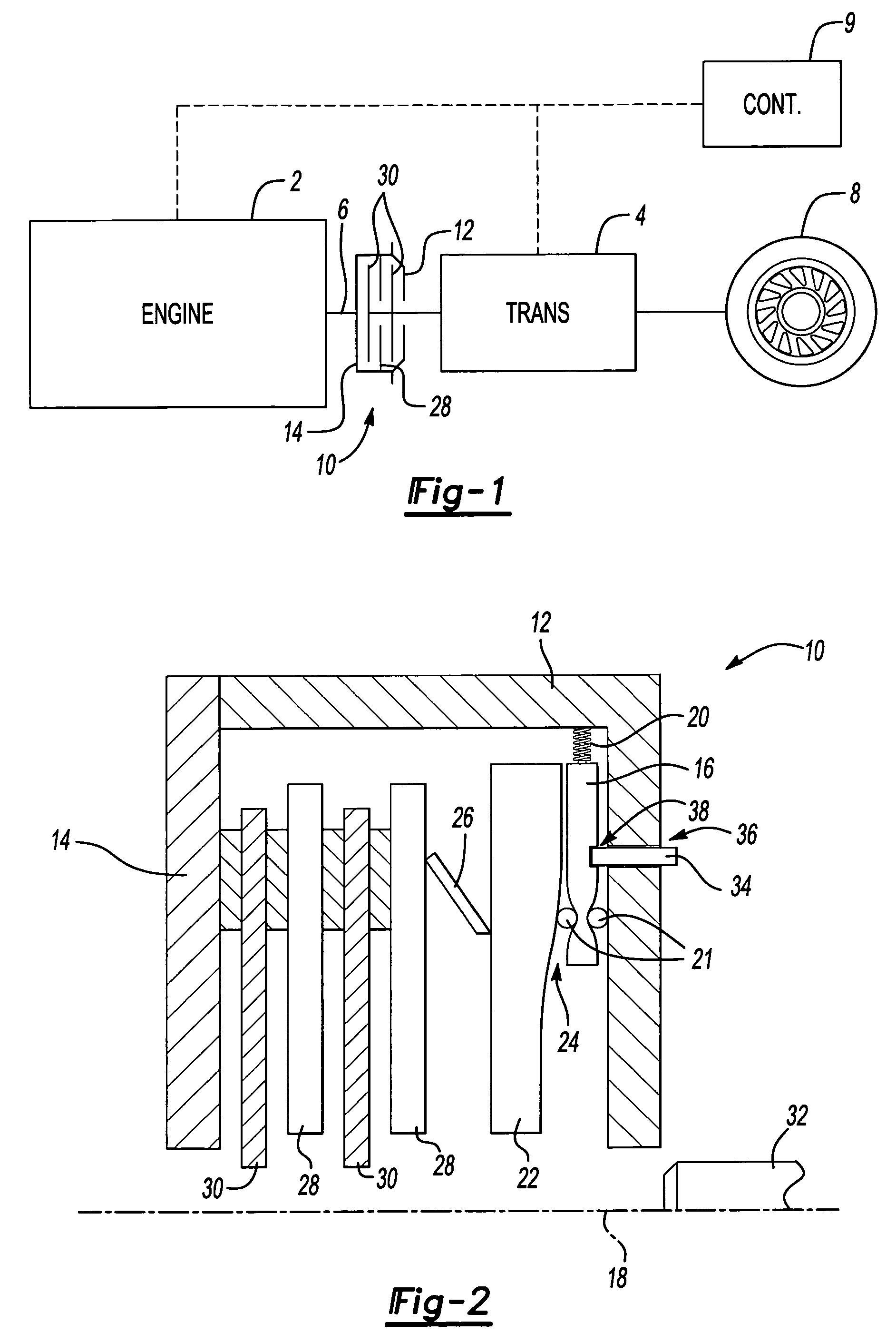
[0016]A powertrain is schematically shown in FIG. 1 and includes an engine 2 and a transmission 4. The engine 2 includes an output shaft for driving the transmission 4, which drives vehicle wheels 8, as known.

[0017]A controller 9 communicates with the engine 2 and transmission 4. The controller 9 commands the engine 2 and transmission 4 in response to parameters stored within the controller 9 and the operating conditions of the engine 2 and transmission 4. The powertrain typically operates in a normal vehicle operating mode. The normal vehicle operating mode may include, for example, engine speed limits to prevent full operating speed while at a stand still. As explained upon, such speed limits can make clutch installation difficult.

[0018]Referring to FIGS. 1 and 2, a clutch assembly 10 includes a clutch cover 12 attached to a flywheel 14. A plurality of centrifugal weights 16 are pivotally mounted within the clutch cover 12 and move radially outward in response to rotation of the c...


PUM


Abstract

A master clutch includes a pressure plate adjacent to a friction disc. A centrifugal weight forces the pressure plate and friction disc into engagement when in a desired install position. A locking device retains the centrifugal weight in the desired installed position. A controller sends an electronic command to a system component, such as an engine, to disengage the locking device. In one example, the electronic command may be an engine speed command that is above an engine speed limit in a normal vehicle operating mode. Commanding the engine to run at a speed greater than the typical engine speed limit moves the centrifugal weight out of the desired installed position making the master clutch operational.

Description

BACKGROUND OF THE INVENTION[0001]This invention relates to a method and apparatus for installing a centrifugal master clutch into a vehicle.[0002]Typically, a normally open clutch assembly includes a rotating input member such as a flywheel, that selectively engages one or more friction discs. The friction discs transmit rotation from the flywheel by one or more pressure plates. A transmission input shaft is driven by rotation of the friction discs. A plurality of centrifugal weights are pivotally mounted to move radially outward in response to rotation of the clutch assembly. As the rotational speed of the clutch assembly increases, rollers on the centrifugal weights are forced up a ramped surface to force engagement of the pressure plates with the friction discs and transmit rotational drive to the input shaft.[0003]Installation of a clutch assembly requires proper alignment between the friction discs and the flywheel. Normally closed clutch assemblies use a biasing force that nor...

Claims


Application Information

Patent Timeline
Patent Type & Authority Patents(United States)
IPC IPC(8): B60W10/02B60W10/04
CPCB60W30/188F16D43/09F16D2250/00F16D2300/12Y10T477/79F16D2500/5116Y10T477/75Y10T477/814F16D2500/3067
Inventor DEVORE, JAMES H.ALLEN, JR., CHARLES E.STURMER, WINFRIEDHEINZELMANN, KARL-FRITZRONGE, LUDGERDREIER, LOREN C.SAYMAN, ROBERT A.MUETZEL, RONALD P.ABUSAMRA, MUNEER
Owner ARVINMERITOR TECH
Learn More