
Feeding mechanism for a microtome

a technology of microtome and feeding mechanism, which is applied in the direction of sawing apparatus, preparing samples for investigation, and withdrawing sample devices, etc., can solve the problems of insufficient usability of cryostat microtome, risk, and inability to allow clearance that is in fact undesirabl

Inactive Publication Date: 2008-01-01
LEICA BIOSYST NUSSLOCH
View PDF20 Cites 13 Cited by
  • Summary
  • Abstract
  • Description
  • Claims
  • Application Information

AI Technical Summary

Benefits of technology

[0007]It is therefore the object of the present invention to develop the feed mechanism for a microtome in such a way that heating of the drive system can be omitted, but a zero-clearance and precise movement between the specimen and the knife is nevertheless possible for adjustment of the cut thickness.
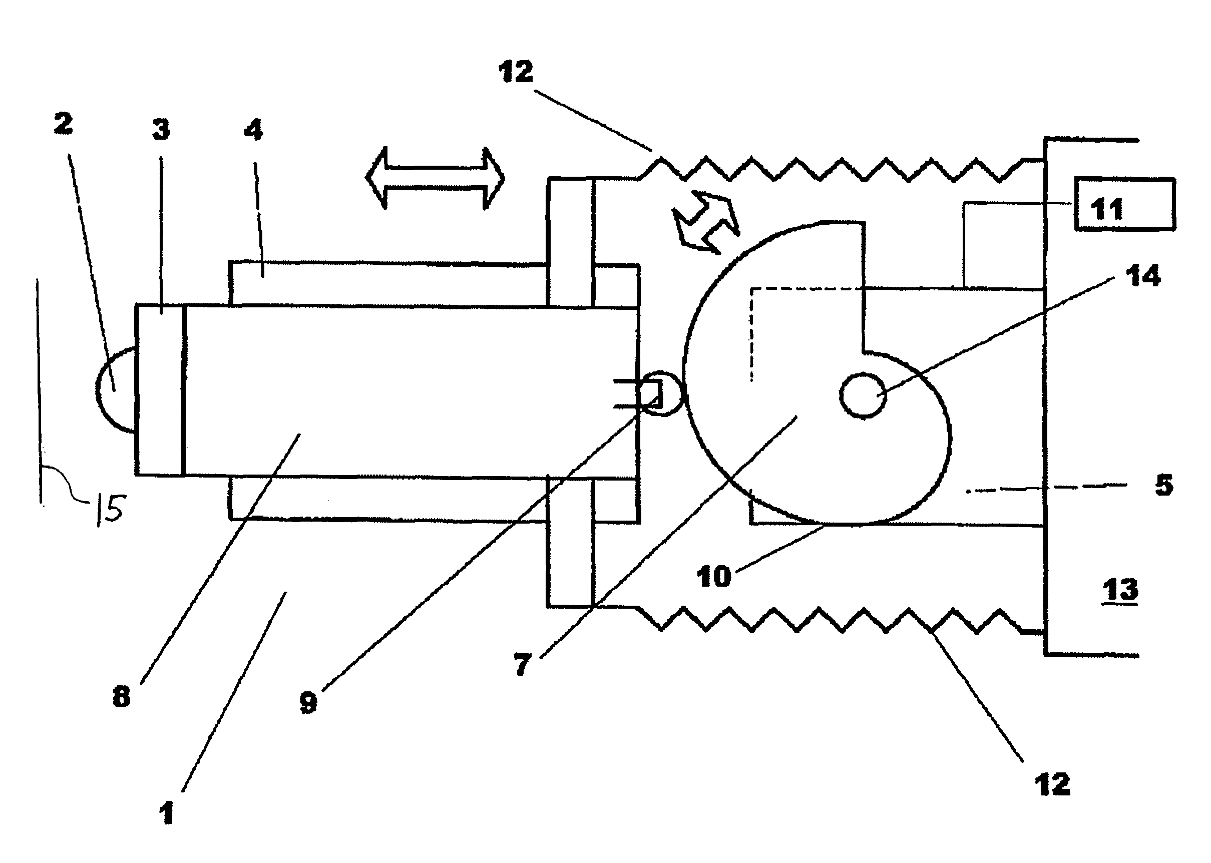
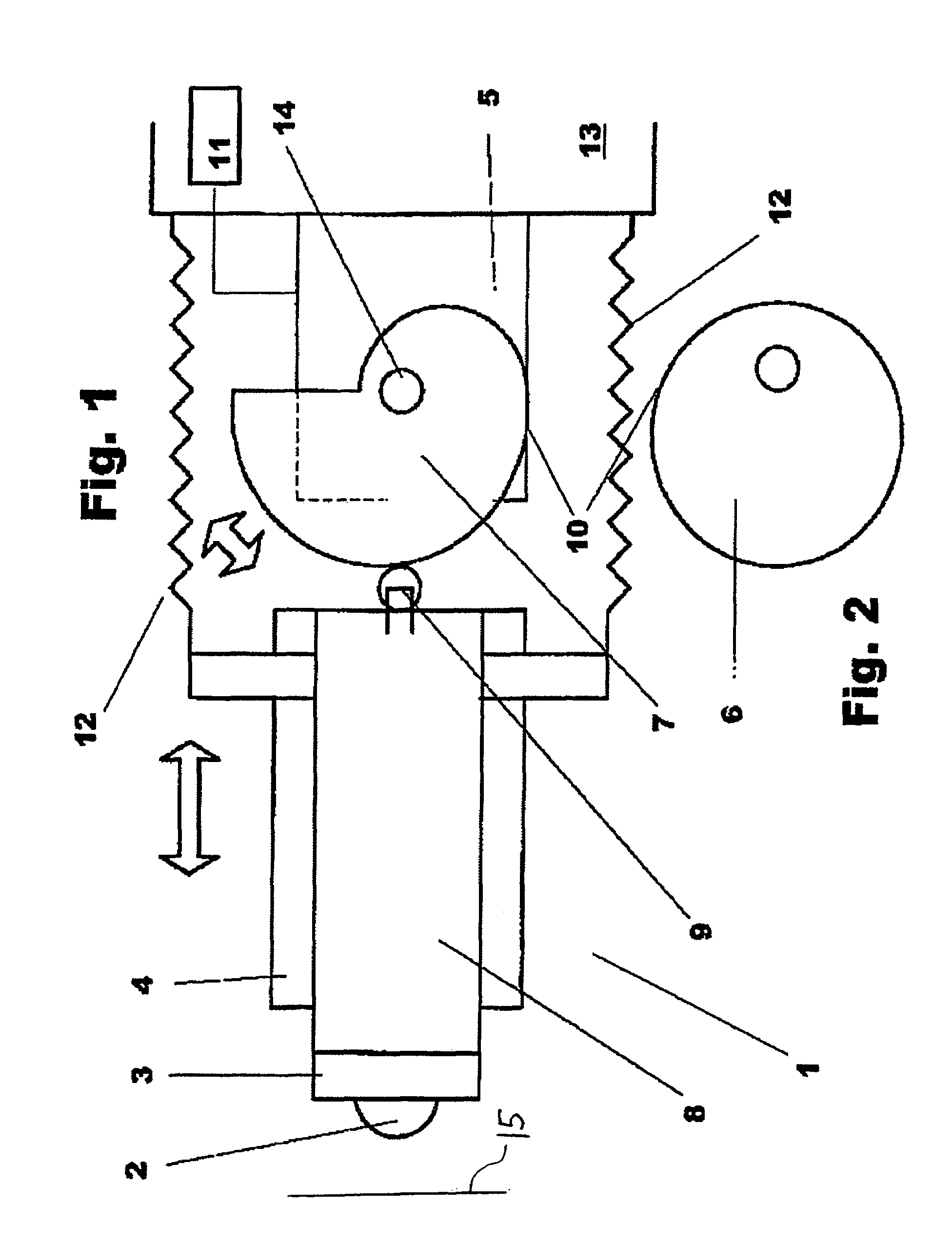
[0009]The invention is characterized in that in order to set the cut thickness of the specimen to be sectioned, the usual spindle drive system has been replaced by a guided slide element and a motorized drive system non-positively connected via an eccentric cam or a helical cam. As a result, temperature-sensitive positive connections for the linear drive system are no longer present. Precision in the advance system is now dependent only on the motor, preferably a stepper motor, and the helical cam or eccentric cam connected thereto. Undesired jamming of the drive system is reliably prevented.

Problems solved by technology

These drive systems have proven successful for microtomes under normal conditions, but are insufficiently usable in cryostat microtomes.
Because of the large temperature differences (from ambient temperature to −60° C.) during operation of a cryostat microtome, and the differing temperature coefficients of the materials used, a clearance that is in fact undesirable must be permitted in the connection between spindle and nut.
Otherwise the risk exists that the drive system will jam.
Encapsulating and heating a microtome in a cryostat of course requires a great deal of complexity.
In addition, a constant temperature setting for the cold portion of the cryostat is not possible with a design of this kind.

Method used


Image

  • Feeding mechanism for a microtome
  • Feeding mechanism for a microtome

Examples


Embodiment Construction

[0016]FIG. 1 shows a feed device 1 for a microtome having a specimen 2 to be sectioned, which is arranged on a specimen holder 3. Specimen holder 3 is mounted on a slide 8 linearly moveable in a slide guide 4, and is configured to be moveable in the double-arrow direction. Arranged on slide 8 at an end opposite specimen 2 is a track roller 9 that runs on outer periphery 10 of a helical cam 7 (see FIG. 1) and is non-positively joined to helical cam 7. For that purpose, a tension spring 12 is arranged between slide 8 and a stationary part 13 of the microtome.

[0017]Helical cam 7 is arranged on a drive shaft 14 of a drive motor 5, which preferably is embodied as a stepper motor and is connected to a control device 11.

[0018]Helical cam 7 is rotated stepwise by motor 5. Track roller 9 thereby rolls on the outer periphery of helical cam 7, and slide 8 is moved linearly in slide guide 4. The non-positive connection between helical cam 7 and track roller 9 is maintained by way of tension spr...


PUM

PropertyMeasurementUnit
temperatureaaaaaaaaaa
thicknessaaaaaaaaaa
relative displacementaaaaaaaaaa

Abstract

A feed device (1) for a microtome, in particular for a cryostat microtome, for setting the cut thickness of the specimen (2) to be sectioned, is described. In order to set the cut thickness, either the cutting knife or the specimen holder (3) is mounted on a slide (8) in a slide guide (4) and is connected non-positively to a drive motor (5). The drive motor (5) is connected either to an eccentric cam (6) or to a helical cam (7), and the nonpositive connection between the motor (5) and the slide is accomplished via the eccentric cam (6) or the helical cam (7).

Description

CROSS REFERENCE TO RELATED APPLICATIONS[0001]This application claims priority of the German patent application 102 10 408.5 which is incorporated by reference herein.FIELD OF THE INVENTION[0002]The invention concerns an advance mechanism for a microtome, in particular for a cryostat microtome, for providing cut thickness displacement between a knife of the microtome and a specimen to be cut.BACKGROUND OF THE INVENTION[0003]Microtomes are designed for precise and thin cutting of preparations for subsequent microscopic examination. For that purpose, a relative motion takes place between the cutting knife and the preparation. Once a cut has been made, the preparation and the knife must be advanced again with respect to one another by an amount equal to the desired cut thickness. This is generally accomplished with a spindle drive system and a movable nut. Rotation of the spindle causes the nut to move, and the desired advance motion takes place between the knife and the preparation or ...

Claims


Application Information

Patent Timeline
Patent Type & Authority Patents(United States)
IPC IPC(8): B23D25/00G01N1/06G01N1/42
CPCG01N1/06G01N1/42G01N2001/065Y10T83/8821Y10T83/6664Y10T83/8805Y10T83/6521
Inventor FOERDERER, KLAUS
Owner LEICA BIOSYST NUSSLOCH
Learn More