
Filter assembly with pleated media V-packs, and methods

a technology of filter media and v-packs, which is applied in the direction of separation process, filtration separation, transportation and packaging, etc., can solve the problems of preventing those skilled in the art of filter design from attempting such a design, no known attempt to use a constant v-pack height multiple, and unsatisfactory panel filters. , to achieve the effect of reducing weight, increasing filter media, and prolonging filter li

Inactive Publication Date: 2007-12-25
DONALDSON CO INC
View PDF26 Cites 49 Cited by
  • Summary
  • Abstract
  • Description
  • Claims
  • Application Information

AI Technical Summary

Benefits of technology

The present patent is about improving filter elements in cylindrical and obround fluid filters by using asymmetrical V-packs with pleated media. The invention provides filters that have increased filter media per given filter volume, extended filter life, and a smaller filter for equivalent filter life. The filters have optimized pleat heights, defined pleat spacing, and optimal shape of the inlet and outlet. The filters are particularly suitable for aircraft cabin applications, which require high unit area filtration, large air flow, and low filter weight. The angle formed by the external edges of adjacent portions is greater than the angle formed by the internal edges of adjacent sections for both standard and reverse flow. The invention also provides a method for cleaning air for an aircraft cabin using the filter element.

Problems solved by technology

However, in some applications, a panel filter is not desirable.
Previously, there have been no known attempts to use a constant pleat height multiple—V-pleat configuration in a cylindrical arrangement.
The disadvantages associated with such a design would prevent those skilled in the art of filters from attempting such a design.
The disadvantages include a decrease in the amount of media that can be packaged within a given volume, and an increase in pressure loss that results from both the higher flow velocities across the media face and the additional inlet and outlet losses at the “V's”.
This results in a large space penalty for this configuration.

Method used


Image

  • Filter assembly with pleated media V-packs, and methods
  • Filter assembly with pleated media V-packs, and methods
  • Filter assembly with pleated media V-packs, and methods

Examples


Embodiment Construction

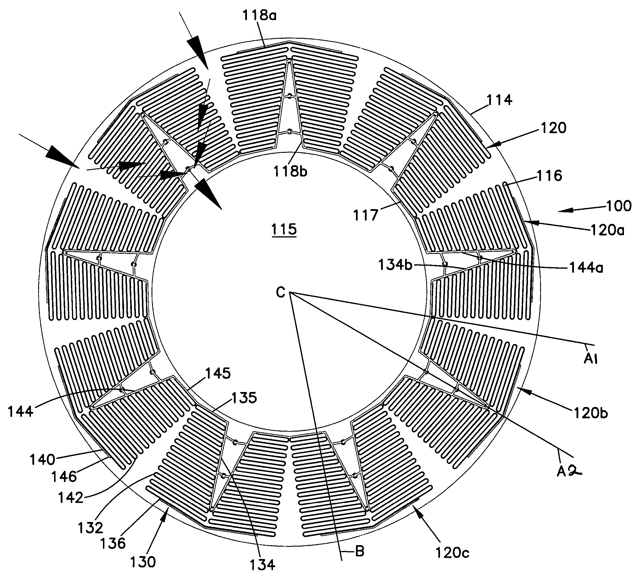
[0032]The present invention is directed to a cylindrical fluid filter element, suitable for use with both gases and liquids. The filter element includes pleated filter media, circularly arranged as “V-packs” or “V-sections”, each of the “V's” having two halves or portions. By use of the term “V”, what is intended is two sections or portions of media, each portion comprising a plurality or multiplicity of folds or pleats. The two portions meet or are joined to form a media construction having a generally “V” shape. A single “V-portion” is illustrated in FIG. 3, and a “V-pack” or “V-section” is illustrated in FIG. 5.

[0033]The two portions of the “V” are symmetrical and are mirror images of one another. By use of the term “symmetrical”, what is intended is that if a central line were drawn through the center of the “V-pack” toward the center point of the filter element, one portion would be on each side of the central line, and each of the portion s would be a mirror image of the other...


PUM

PropertyMeasurementUnit
angleaaaaaaaaaa
edge angleaaaaaaaaaa
angleaaaaaaaaaa

Abstract

A generally cylindrical filter element incorporating nonsymmetrical or asymmetrical V-pleated media. The V-pleated media provides increased filter media per given filter volume, extended filter life, and a smaller filter for equivalent filter life. A smaller filter is generally beneficial for some applications such as aircraft, due to its lower weight. Various features of the filter include asymmetric variable pleat heights applied to a cylindrical or obround filter; defined pleat spacing applied to a variable pleat height element; optimal pleat density; and optimal shape of inlet and outlet.

Description

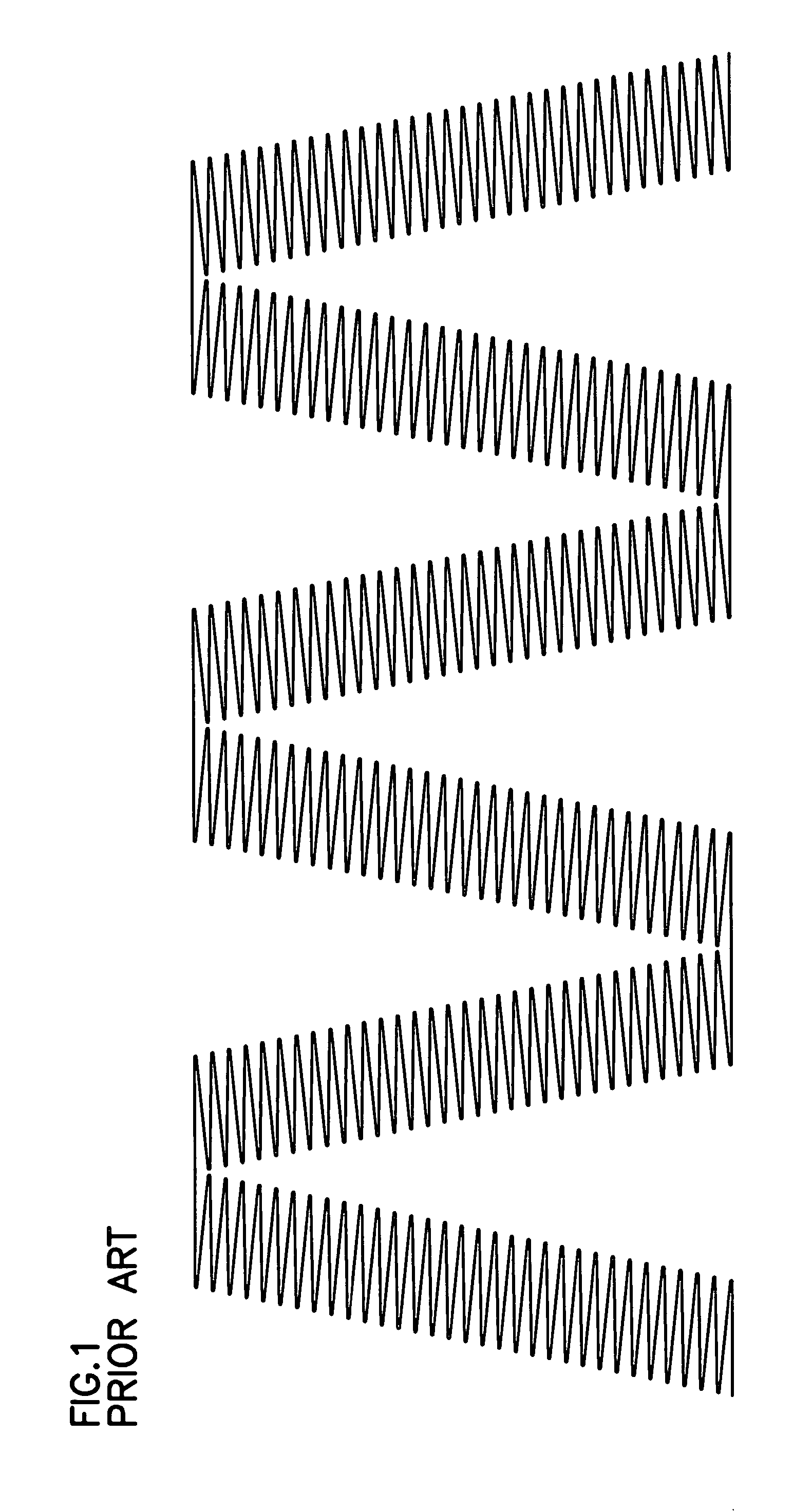
[0001]This application claims priority under 35 U.S.C. § 119(e) to provisional application Ser. No. 60 / 511,264, filed Oct. 14, 2003. The complete disclosure of application Ser. No. 60 / 511,264 is incorporated by reference herein.FIELD[0002]The present invention relates to pleated filter media for use in fluid filters. In particular, the invention relates to pleated filter media for use in cylindrical and obround fluid filters.BACKGROUND[0003]Panel air filters having a multiple V-pleat configuration are commercially available from various sources such as Donaldson Company, Inc., Pall Corp., TriDim Filter Corp., and Koch Filter Corp. A partial section of a multiple V-pleat panel, having a constant pleat height, is shown in FIG. 1. Multiple V-pleat panel configurations are known to greatly improve performance in a panel filter having an axial flow configuration.[0004]It is well established in the filter industry that by decreasing pleat height and increasing pleat density, additional me...

Claims


Application Information

Patent Timeline
Patent Type & Authority Patents(United States)
IPC IPC(8): B01D46/00B01D29/21B01D46/52
CPCB01D29/21B01D46/125B01D46/522B01D29/213B01D2201/127B01D2265/06B01D46/121
Inventor ADAMEK, DANIEL ERICGUSTAFSON, MICHAEL JONMILLS, JARREN B.SCHNIEDER, KIRK A.WELCH, MARILYN D.
Owner DONALDSON CO INC
Learn More