
Room air purifier with pressurization relief

a technology of air purifier and pressurization relief, which is applied in the direction of lighting and heating apparatus, heating types, separation processes, etc., can solve the problems of health care costs of tens of billions of dollars and productivity loss at work for the united states

Active Publication Date: 2016-02-09
MILLER GREGORY R
View PDF24 Cites 13 Cited by
  • Summary
  • Abstract
  • Description
  • Claims
  • Application Information

AI Technical Summary

Benefits of technology

This patent describes an air purification system that is designed to clean the air before it enters a room. The system can also re-clean the air in the room and prevent air from outside the room from entering through a door. Additionally, it can control the temperature of the room and monitor the air pressure to alert the user and automatically manage the system. The system can also be turned off or unplugged while still installed, and allows air from a forced air supply duct to flow freely into the room without coming into contact with the filters. The system can communicate with other air purification systems and can manage and take responsibility for corrective action for other systems. Overall, the air purification system provides effective control of air quality in a room.

Problems solved by technology

The cost to the United States is tens of billions of dollars in health care and lost productivity at work.

Method used


Image

  • Room air purifier with pressurization relief
  • Room air purifier with pressurization relief
  • Room air purifier with pressurization relief

Examples


Embodiment Construction

” one will understand how the features of various embodiments are used.

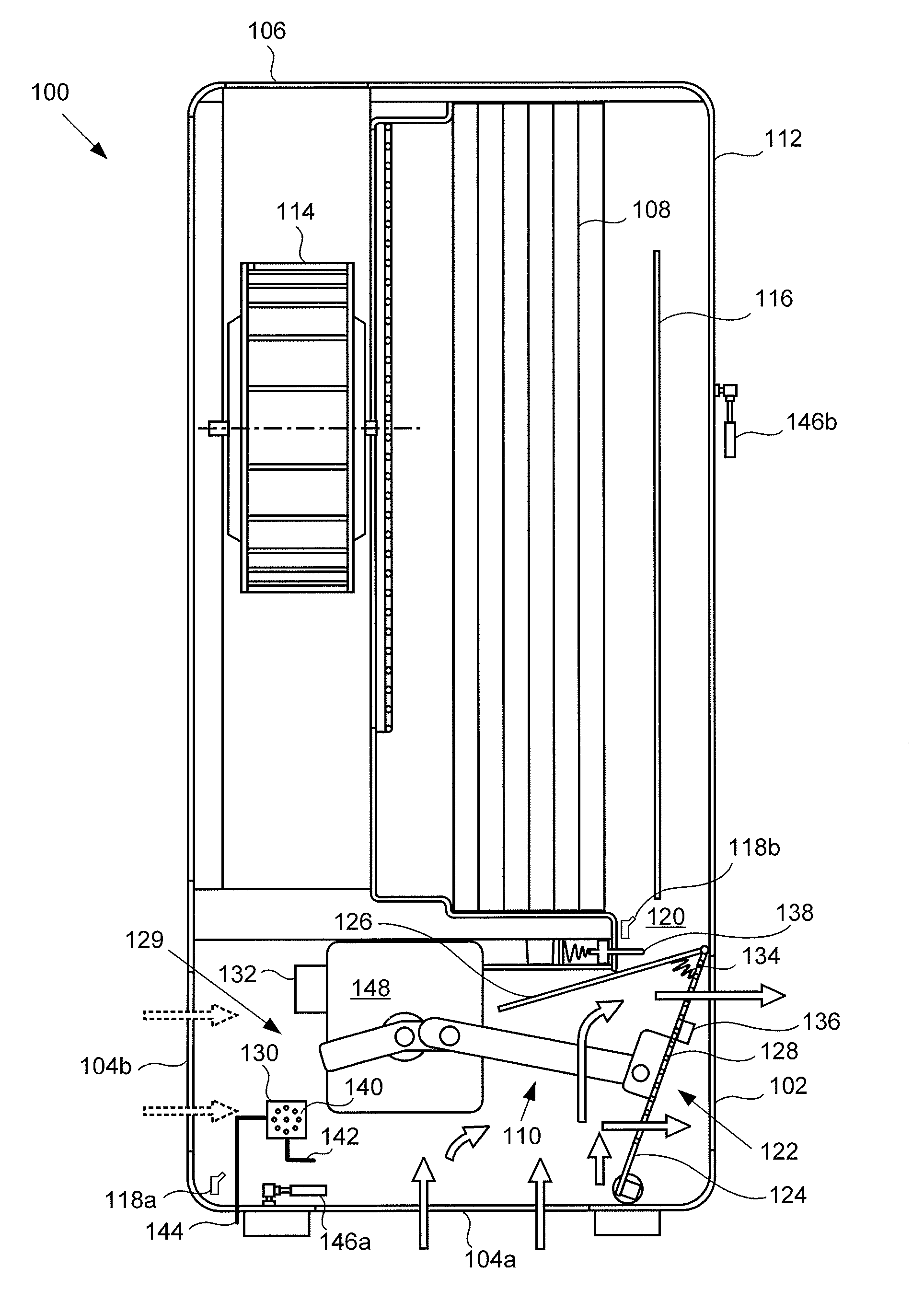
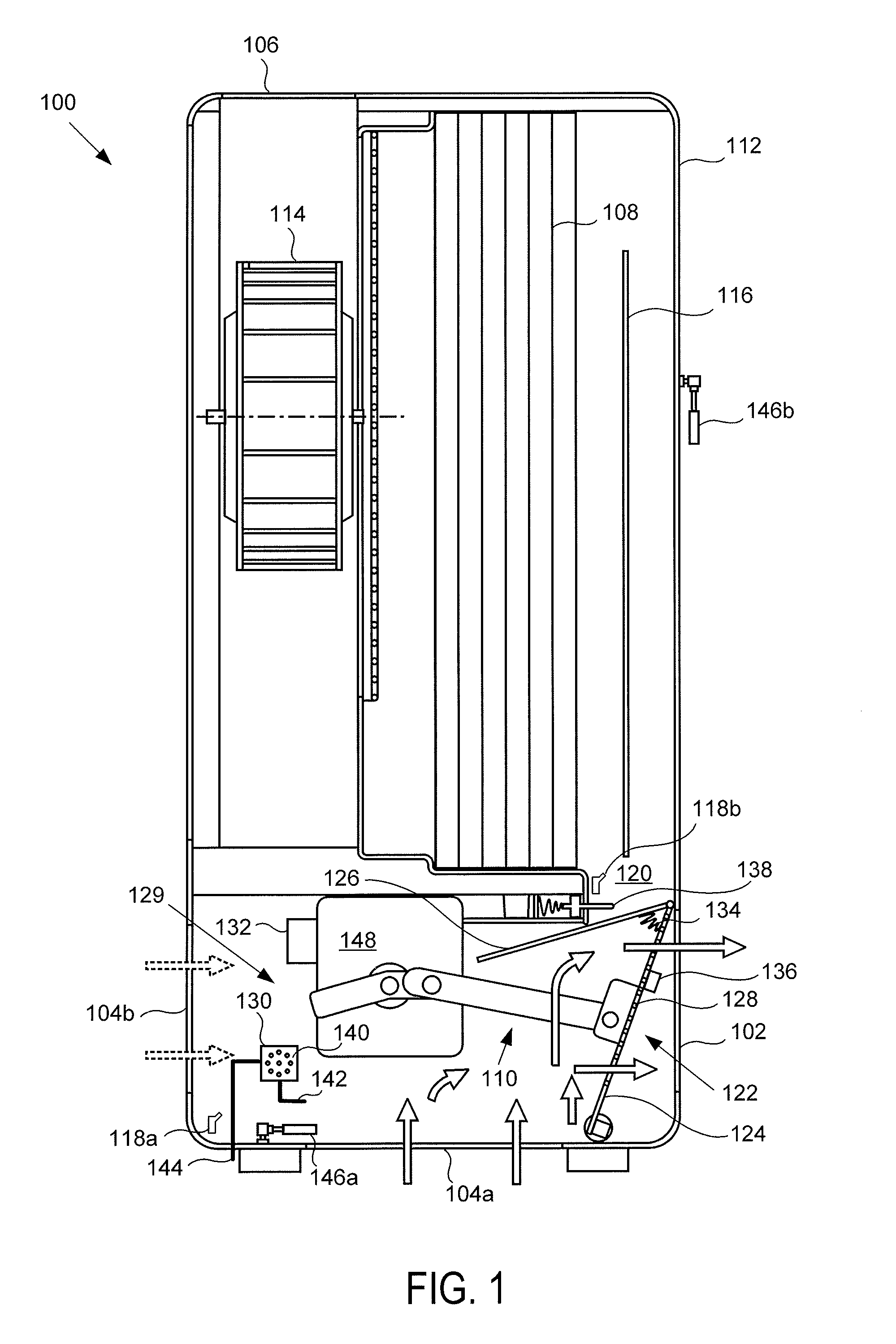
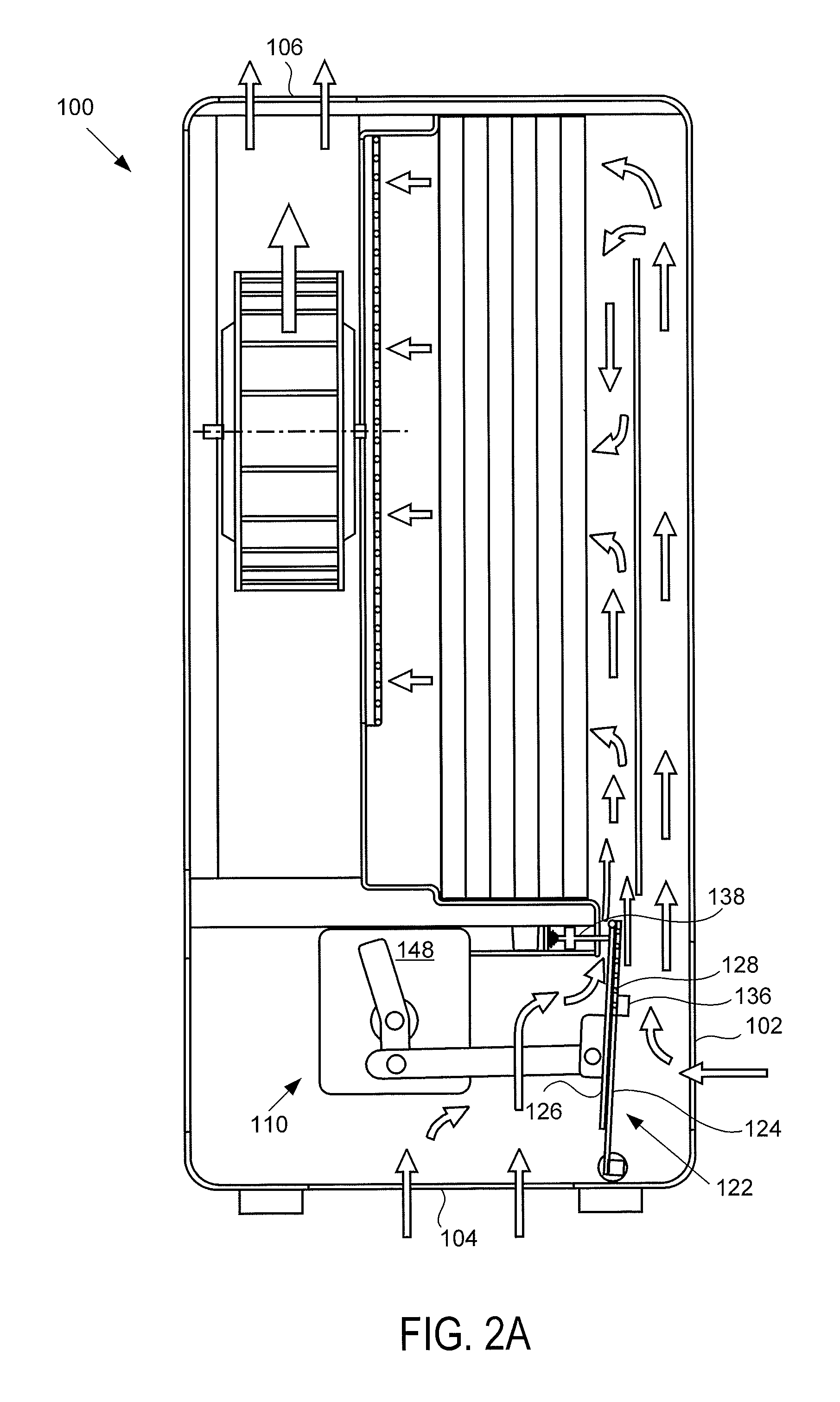
[0007]One aspect of the disclosure is an air purification system with over pressurization relief capabilities including the following components. A room air inlet is configured to fluidly receive air from a room. A supply duct inlet is configured to fluidly receive air from a forced air system. An air filter / purifier is configured to filter / purify air. An outlet is configured to expel filtered / purified air into the room. A bypass damper system has at least one air filtering mode position and a bypass mode position. A pressure control mechanism is configured to automatically allow the bypass damper system to move from at least one air filtering mode position to a bypass mode position when the air received from the supply duct inlet exceeds a bypass threshold. Furthermore, at least one air filtering mode position guides air from the supply duct inlet and air from the room air inlet to both pass through the filter a...


PUM

PropertyMeasurementUnit
temperaturesaaaaaaaaaa
point temperatureaaaaaaaaaa

Abstract

Systems and methods are provided for an air purifier with over pressurization relief, including the following components. A room air inlet is configured to fluidly receive air from a room. A supply duct inlet is configured to fluidly receive air from a forced air system. An air filter and or air purification means is configured to filter / purify air. An outlet is configured to expel filtered / treated air into the room. A bypass damper system has at least one air filtering mode position and a bypass mode position. A pressure control mechanism is configured to automatically allow the bypass damper system to move from at least one air filtering mode position to a bypass mode position when the air received from the supply duct inlet exceeds a bypass threshold. The bypass mode position guides air from the supply duct inlet into the room without requiring passage through the filter and the outlet.

Description

TECHNICAL FIELD[0001]The disclosed embodiments relate generally to purification of air and, more specifically to provide a room air purifier with pressurization relief.BACKGROUND[0002]Indoor air quality ranks among the top five environmental risks to humans in the United States. The costs are measured in tens of millions of people suffering from allergies and asthma and more formidable airborne VOCs, gases, and other contaminants. The cost to the United States is tens of billions of dollars in health care and lost productivity at work. For instance, the EPA has an exhaustive list of the consequences of poor indoor air quality. As such, it is desirable to provide solutions to indoor air quality.SUMMARY[0003]Treating air provided from forced air heating and / or cooling systems, which are commonly found in roughly 80% of the homes in the United States (per US Census data) is one way to address improving the above described indoor air quality issues. Furthermore, when dealing with forced...

Claims


Application Information

Patent Timeline
Patent Type & Authority Patents(United States)
IPC IPC(8): B01D29/62F24F3/16B01D46/44B01D46/00B01D35/147B01D35/143F24F11/02F24F11/00F24F8/10
CPCB01D46/0087B01D46/0032B01D46/0086B01D46/446B01D46/448F24F3/1603F24F11/022F24F2003/1682F24F2011/0042F24F2110/40F24F11/72F24F8/30F24F8/10
Inventor MILLER, GREGORY, R.
Owner MILLER GREGORY R
Learn More