
Storm top detection

Active Publication Date: 2007-12-11
ROCKWELL COLLINS INC
View PDF18 Cites 89 Cited by
  • Summary
  • Abstract
  • Description
  • Claims
  • Application Information

AI Technical Summary

Benefits of technology

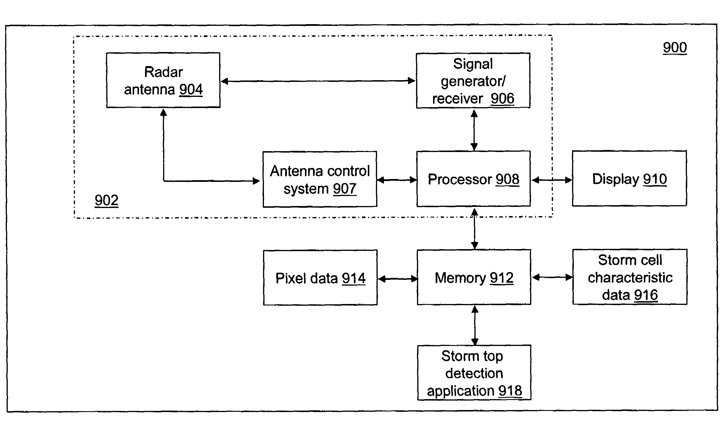
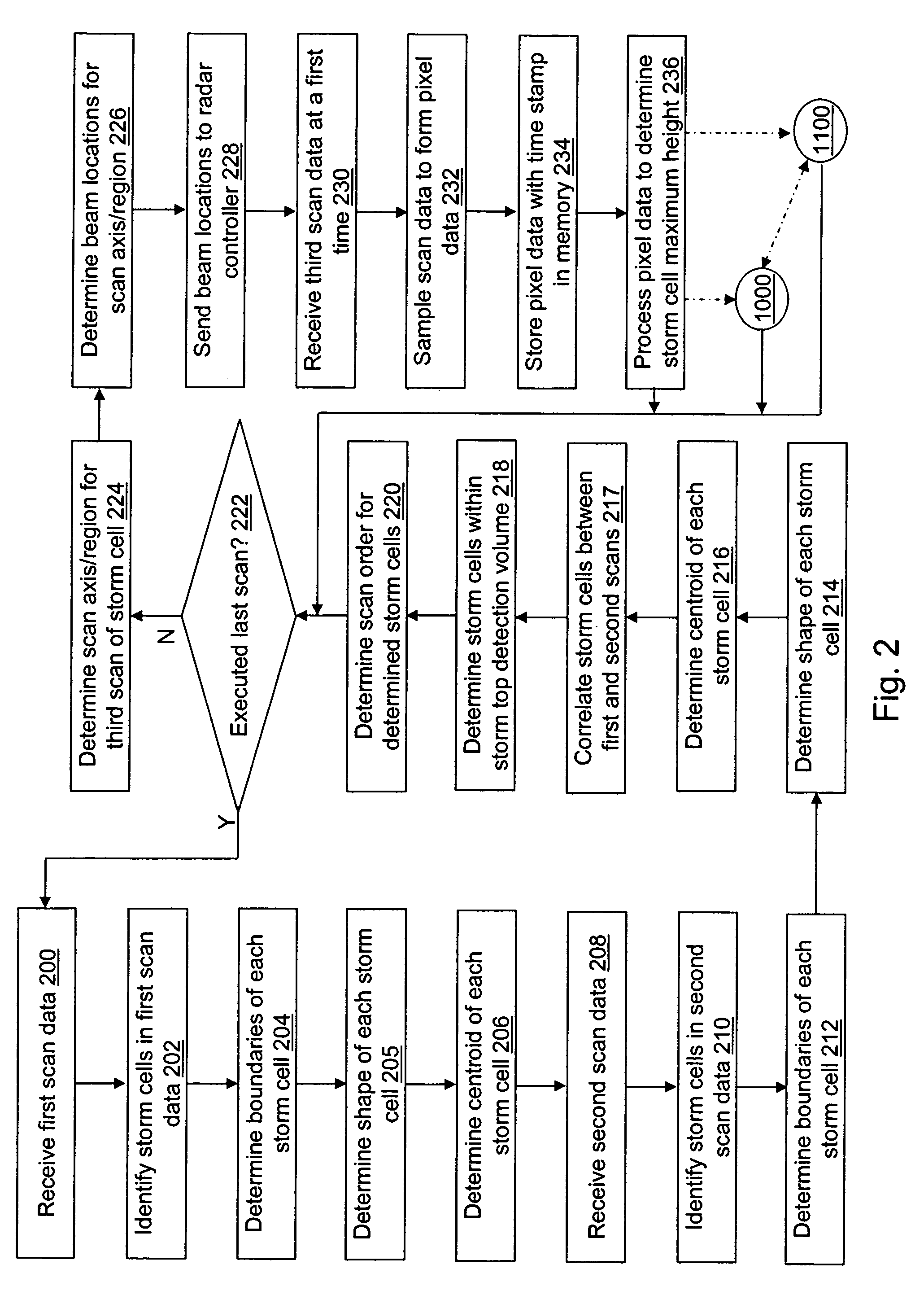
[0006]An exemplary embodiment provides a method and a system for efficiently detecting a maximum height of a storm cell. The method and system may further provide prediction of the change in height of the storm cell so that the aircraft can avoid the storm cell, if necessary. The system includes, but is not limited to, an antenna adapted to receive signals reflected from a storm cell; a receiver coupled to the antenna and adapted to process the received signals thereby forming reflectivity data associated with a scan of the storm cell; a processor coupled to the receiver; and a memory operably coupled to the processor. The processor is configured to receive first reflectivity data from the receiver formed from a first scan of the storm cell; identify a first centroid of the storm cell based on the received first reflectivity data; receive second reflectivity data from the receiver formed from a second scan of the storm cell; identify a second centroid of the storm cell based on the received second reflectivity data; determine a scan axis for a third scan of the storm cell based on the first centroid and the second centroid; send the determined scan axis to a radar controller adapted to control execution of the third scan; receive third reflectivity data from the receiver formed from the third scan of the storm cell at a first time; sample the received third reflectivity data to form pixel data; and process the formed pixel data to determine a first maximum height of the storm cell. The pixel data comprises a plurality of pixels, wherein each pixel of the plurality of pixels identifies a segment of the third reflectivity data. A reflectivity indicator is determined for each pixel. The memory receives and stores the pixel data.

Problems solved by technology

Storm tops are hazards to aircraft.
Turbulence is the leading cause of in-flight injuries to passengers and cabin crews on aircraft.
A high turbulence region exists above a storm cell, but is difficult to detect with radar due to the low reflectivity.

Method used


Image

  • Storm top detection
  • Storm top detection
  • Storm top detection

Examples


Embodiment Construction

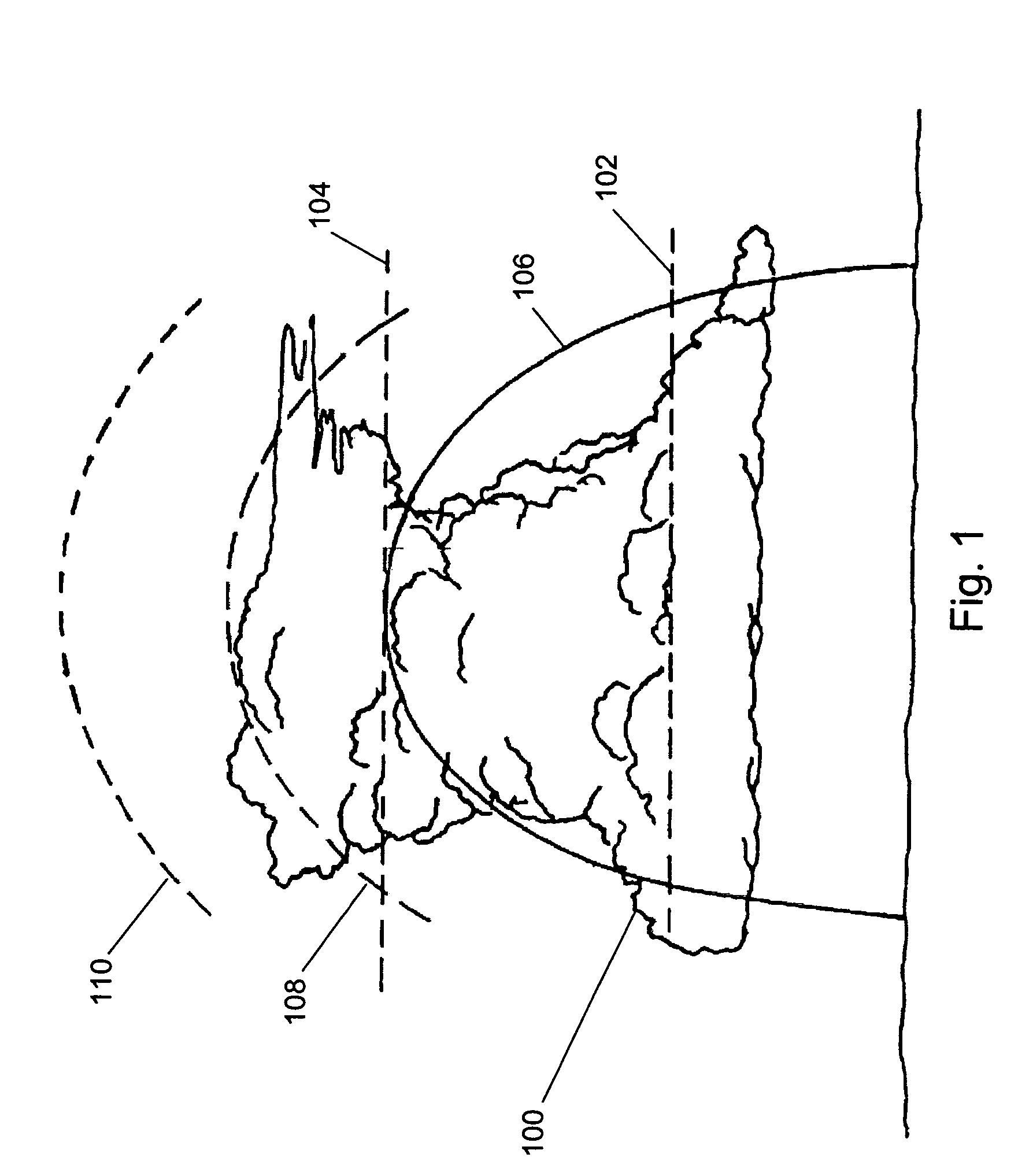
[0020]With reference to FIG. 1, a diagram illustrating the spatial distribution of a typical thunderstorm 100 is shown. The portion of thunderstorm 100 below a first altitude 102 contains water in liquid form. The portion of thunderstorm 100 below a second altitude 104 and above first altitude 102 contains a mixture of ice and water in liquid form. The portion of thunderstorm 100 above second altitude 104 contains only ice. Most of the reflectivity of a storm originates from the moisture that it contains and often the top of the storm is significantly higher than the moisture based radar reflectivity indicates. As a result, based on the geometry of thunderstorm 100, regions may be defined by their ability to be detected by radar, their visibility to a pilot, and their effect on an aircraft. Region 106, which includes the liquid water and the mixed ice and water portions of thunderstorm 100, is a region that is detectable by an aircraft radar system, due to the high and moderate rada...


PUM


Abstract

A method of characterizing a maximum height of a storm cell for an aircraft is provided. First reflectivity data formed from a first scan of a storm cell by a radar is received and a first centroid of the storm cell is identified. Second reflectivity data formed from a second scan of the storm cell by the radar is received and a second centroid of the storm cell is identified. A scan axis for a third scan of the storm cell based on the first centroid and the second centroid is determined. Third reflectivity data formed from the third scan of the storm cell by the radar at a first time is received. The third reflectivity data is sampled to form pixel data that includes a reflectivity indicator determined for each pixel formed from the third reflectivity data. A maximum height of the storm cell is determined by processing the pixel data.

Description

BACKGROUND OF THE INVENTION[0001]The present application relates generally to weather detection. More particularly, the present application relates to the detection of storm tops.[0002]Thunderstorms are a violent example of atmospheric convection with the uplift and cooling of air and subsequent cloud formation. As the cloud forms, water vapour changes to liquid and / or to frozen cloud particles resulting in a large release of heat that becomes the principal source of energy for the developing cloud. The cloud particles grow by colliding and combining with each other, forming rain, snow, and / or hail. High level winds may shear the cloud top into an anvil shape. When the droplets become heavy enough to fall against the updraft created as the cloud forms, precipitation begins. Once precipitation begins the updraft which initiated the cloud's growth weakens and is joined by a downdraft generated by the precipitation. This updraft-downdraft couplet constitutes a single storm cell. A typi...

Claims


Application Information

Patent Timeline
IPC IPC(8): G01S13/95G01S13/00
CPCG01S13/953G01S7/411G01W2001/003Y02A90/10
Inventor KRONFELD, KEVIN M.WOODELL, DANIEL L.
Owner ROCKWELL COLLINS INC
Learn More