
Layer configuration comprising an electron-blocking element

Inactive Publication Date: 2007-12-11
AGFA GEVAERT AG
View PDF11 Cites 15 Cited by
  • Summary
  • Abstract
  • Description
  • Claims
  • Application Information

AI Technical Summary

Benefits of technology

[0012]It has been surprisingly found that the use of an element containing an organic polymer containing covalently bonded sulphonic acid groups, sulphate groups, carboxy groups, optionally quaternized amine groups or phosphonic acid groups between a positive electrode and a material capable of hole transport improves the device performance by increasing the lifetime.

Problems solved by technology

A general problem in electronic devices, particularly in light emitting diodes, is undesirable hole-electron recombination at the positive electrode thereby reducing the efficiency and lifetime of the device.

Method used


Image

  • Layer configuration comprising an electron-blocking element
  • Layer configuration comprising an electron-blocking element
  • Layer configuration comprising an electron-blocking element

Examples


first embodiment

[0041]According to the layer configuration, according to the present invention, the at least one polymer is a copolymer with a non-carboxy, non-amino, non-sulphato, non-sulpho, non-vinylphosphonic acid containing comonomer.

second embodiment

[0042]According to the layer configuration, according to the present invention, the thickness of the element is between 1 and 20 nm.

third embodiment

[0043]According to the layer configuration, according to the present invention, the at least one polymer is a copolymer with a non-carboxy, non-amino, non-sulphato, non-sulpho, non-vinylphosphonic acid containing comonomer and the thickness of the element is between 1 and 20 nm.


PUM

PropertyMeasurementUnit
Massaaaaaaaaaa
Fractionaaaaaaaaaa
Timeaaaaaaaaaa

Abstract

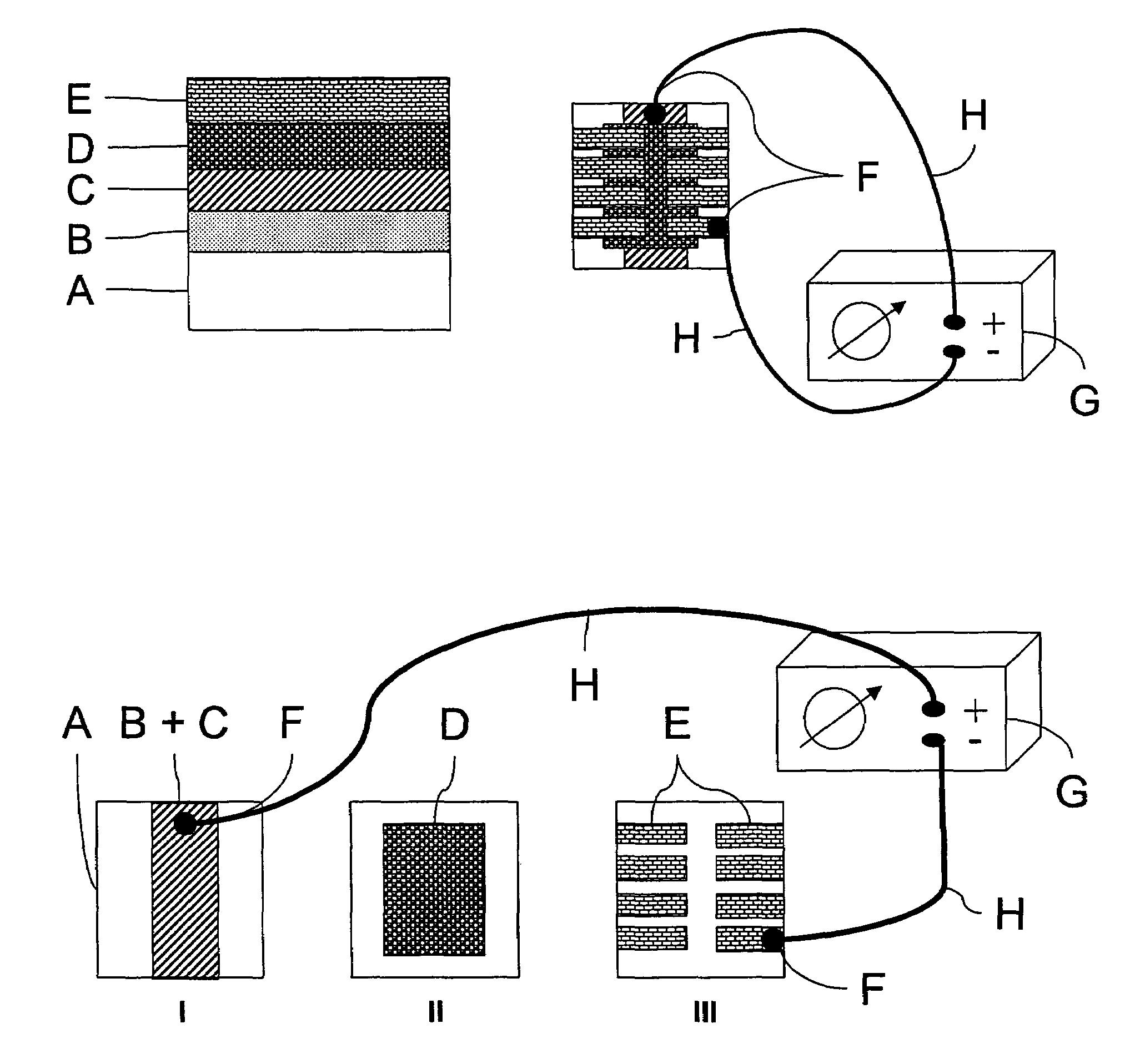
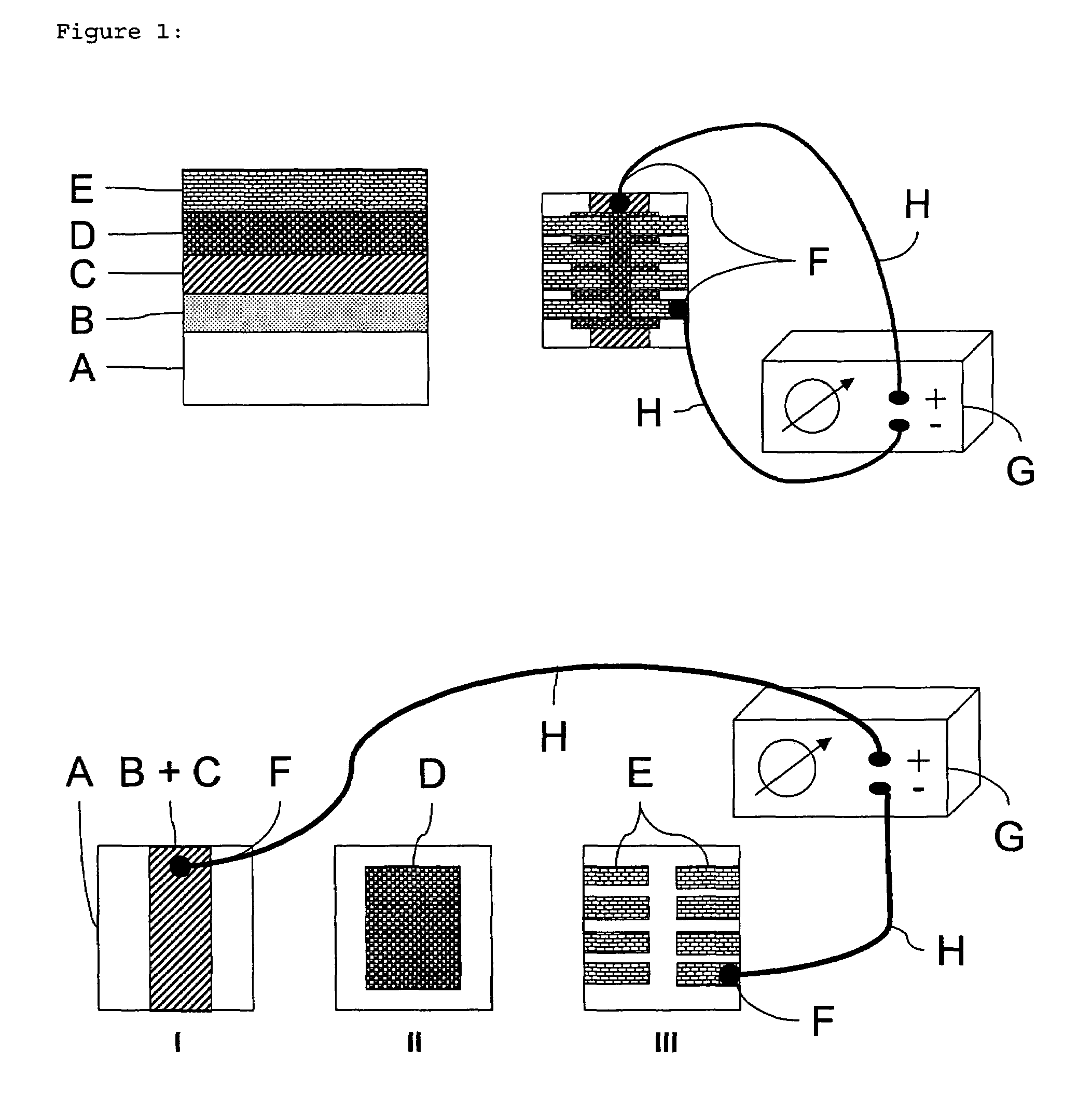
A layer configuration on a support, the layer configuration comprising a non-photoactive element exclusive of unsubstituted poly(3,4-alkylenedioxythiophene)s, the element containing at least one polymer selected from the group consisting of polycarboxy-polymers, optionally quaternized polyamine-polymers and poly(vinylphosphonic acid), the surface of one side of the element being contiguous with a positive electrode and the surface on the opposite side of the element being contiguous with a material capable of transporting holes.

Description

[0001]This application claims the benefit of U.S. Provisional Application No. 60 / 409,793 filed Sep. 11, 2002, which is incorporated by reference. In addition, this application claims the benefit of European Application No. 02102215.7 filed Aug. 23, 2002, which is also incorporated by reference.FIELD OF THE INVENTION[0002]The present invention relates to a layer configuration comprising an electron-blocking element.BACKGROUND OF THE INVENTION[0003]U.S. Pat. No. 4,175,982 discloses a photovoltaic device comprising a first, ohmic electrode and a second barrier electrode and sandwiched therebetween a photoactive layer comprising metal-free phthalocyanine dispersed in an electrically insulating binder, e.g. poly(N-vinyl carbazole), polyvinylacetate, polycarbonate, polystyrene, polystyrene acrylonitrile copolymer and polyacrylonitrile, wherein the barrier electrode comprises a metal the oxide of which is electrically conductive.[0004]WO 00 / 06665 discloses an electroluminescent device comp...

Claims


Application Information

Patent Timeline
IPC IPC(8): H01L51/52C08G61/12C08G73/02C08G73/06C09K11/06C09K11/54C09K11/56C09K11/77H01B1/12H01L51/00H01L51/05H01L51/30H01L51/42H01L51/50H05B33/14H05B33/22
CPCC08G61/126C08G73/0611C09K11/06C09K11/54C09K11/565C09K11/7716H01B1/127H01L51/0037H05B33/14H05B33/22C08G73/0266Y02E10/549H01L51/0036H01L51/0038H01L51/0039H01L51/0042H01L51/0059H01L51/0504H01L51/42H01L51/5096H10K85/115H10K85/146H10K85/1135H10K85/114H10K85/113H10K85/631H10K50/18H10K10/40H10K30/50H10K10/00H10K30/00
Inventor ANDRIESSEN, HIERONYMUS
Owner AGFA GEVAERT AG
Learn More