
Staged combustion system with ignition-assisted fuel lances

a technology of ignition-assisted fuel lances and combustion systems, which is applied in the direction of combustion types, combustion using lumps and pulverizing fuel, lighting and heating apparatus, etc., can solve the problems of high nosub>x /sub>emissions, unburned fuel, and/or unburned fuel

Active Publication Date: 2007-12-04
AIR PROD & CHEM INC
View PDF58 Cites 29 Cited by
  • Summary
  • Abstract
  • Description
  • Claims
  • Application Information

AI Technical Summary

Benefits of technology

The invention relates to a combustion system with a furnace and a combustion atmosphere. The system includes one or more fuel lances and igniters for igniting the fuel. The igniters can be intermittent or continuous spark igniters, DC arc plasmas, microwave plasmas, RF plasmas, high energy laser beams, or oxidant-fuel pilot burners. The igniters can be associated with the fuel lances or integrated into them. The system can also include one or more oxidant gas injectors for introducing oxidant gas into the furnace. The distance between the oxidant gas injector and the fuel lance can be in the range of 2 to 50 inches. The technical effects of the invention include improved flame ignition, improved fuel atomization, and improved combustion efficiency.

Problems solved by technology

Improper control of flame stability and flame location in staged combustion systems, particularly during cold startup, process upsets, or turndown conditions, may result in undesirable combustion performance, higher NOx emissions, and / or unburned fuel.
This latter condition could lead to substantial pockets of fuel in the furnace and the possibility of an uncontrolled energy release.

Method used


Image

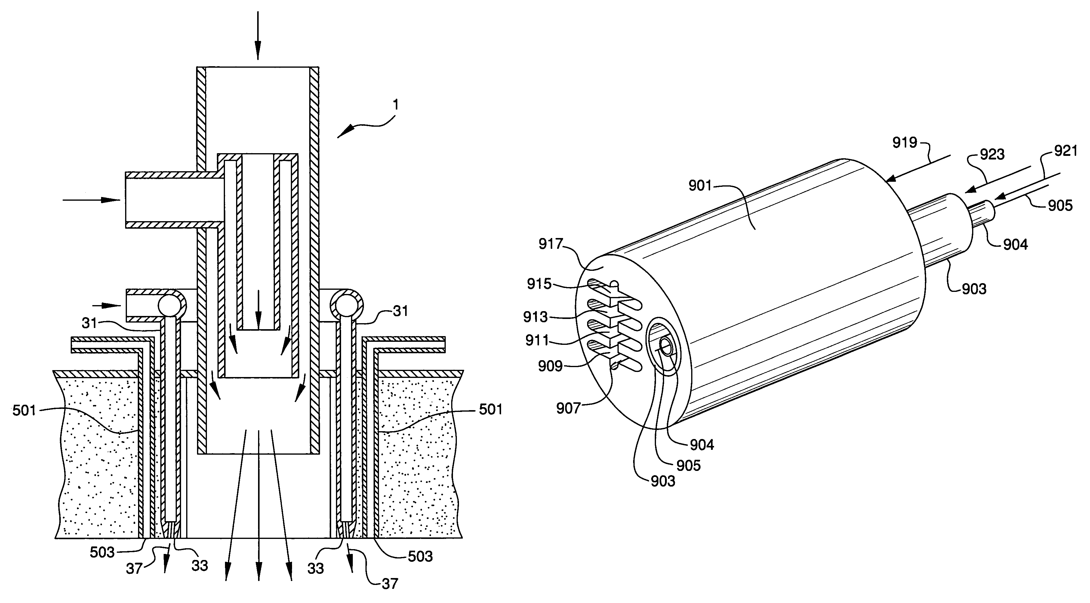
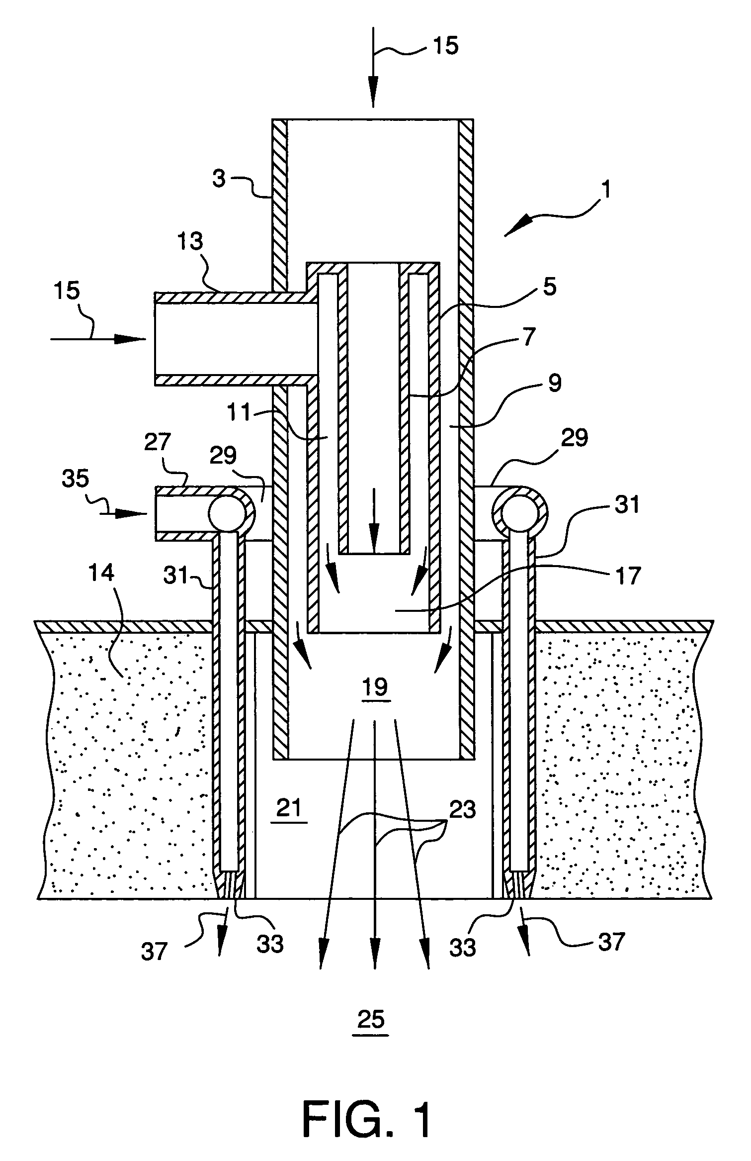
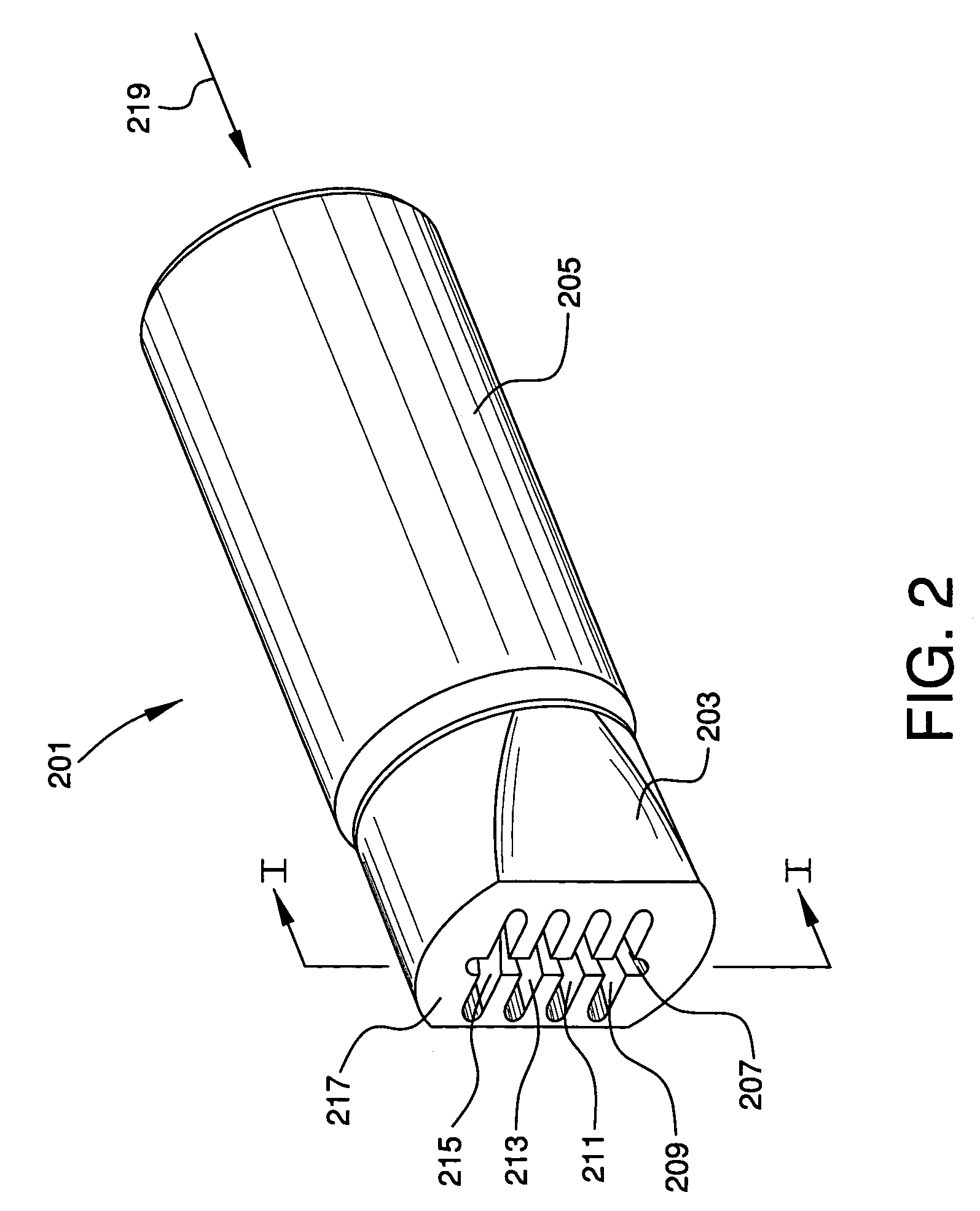
  • Staged combustion system with ignition-assisted fuel lances
  • Staged combustion system with ignition-assisted fuel lances
  • Staged combustion system with ignition-assisted fuel lances

Examples


Embodiment Construction

[0056]Combustion-based processes utilize the combustion of fuel streams with oxygen to generate process heat and, in some cases, to consume combustible off-gas streams from other process systems. In the establishment of a combustion reaction with these various fuels, autoignition will occur if the temperature of the fuel-oxidant mixture is above the autoignition temperature of the mixture. In air / natural gas mixtures, for example, the autoignition temperature is about 1,000° F. An ignition source is required to initiate the combustion reaction if the temperature of the fuel-oxidant mixture is below its autoignition temperature.

[0057]An additional variable, the extent of mixing in the combustion atmosphere or combustion region, can affect the stability of the combustion process with a gaseous or vaporized fuel. Stabilization of the combustion process becomes complicated when fuel staging is used to limit formation of NOx. In fuel staging, raw fuel (without air or oxygen) is introduce...


PUM


Abstract

Combustion system comprising a furnace having a thermal load and a combustion atmosphere disposed therein; one or more fuel lances adapted to inject fuel into the combustion atmosphere; and one or more igniters associated with the one or more fuel lances and adapted to ignite the fuel injected by the one or more fuel lances into the combustion atmosphere.

Description

BACKGROUND OF THE INVENTION[0001]Staged combustion systems are used to improve combustion by introducing successive portions of fuel into the combustion process to allow the oxidant and fuel to react in multiple zones or stages. This produces lower peak flame temperatures and other favorable combustion conditions that reduce the generation of nitrogen oxides (NOx). A wide variety of staged combustion methods are known and used in combustion applications including process heaters, furnaces, steam boilers, gas turbine combustors, coal-fired power generation units, and many other combustion systems in the metallurgical and chemical process industries.[0002]The combustion of a gaseous fuel with oxygen in an oxygen-containing gas such as air occurs when a fuel-oxygen-inert gas mixture having a composition in the combustible region reaches its autoignition temperature or is ignited by a separate ignition source. When the combustion occurs in a three-dimensional process space such as a fur...

Claims


Application Information

Patent Timeline
Patent Type & Authority Patents(United States)
IPC IPC(8): F23D5/00F23D14/22F23D14/32F23D14/58
CPCF23D14/22F23D14/583F23D14/32F23C2201/30Y02E20/344F23D2203/1026F23D14/48
Inventor JOSHI, MAHENDRA LADHARAMSLAVEJKOV, ALEKSANDAR GEORGILI, XIANMING JIMMY
Owner AIR PROD & CHEM INC
Learn More