
Method for managing engine torque during a gear shift in an automatic shift manual transmission

a gear shift and manual transmission technology, applied in the direction of machines/engines, non-automatic control, electrical control, etc., can solve the problems of undesirable speed flare, insufficient torque authority provided by spark timing, engine is temporarily unable to provide operator-demanded torque, etc., to achieve the effect of torque reduction

Inactive Publication Date: 2007-11-27
FORD GLOBAL TECH LLC
View PDF18 Cites 57 Cited by
  • Summary
  • Abstract
  • Description
  • Claims
  • Application Information

AI Technical Summary

Benefits of technology

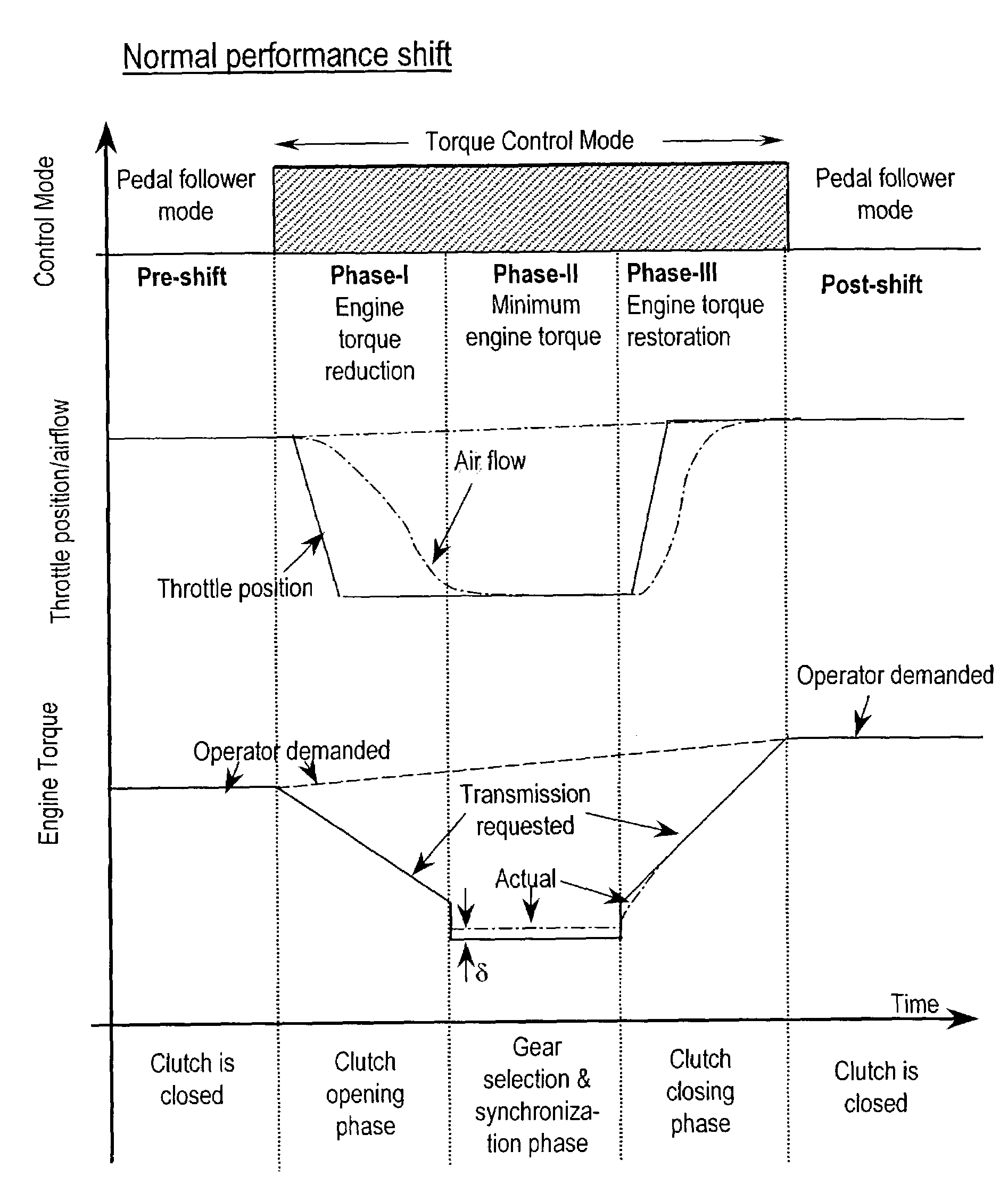
[0014]According to another aspect of the present invention, fast actuators, such as spark timing and a valve timing adjustment mechanism, are adjusted so that the actual torque trajectory during the torque reduction phase of the gearshift event matches the transmission requested torque trajectory. Fast actuators are those in which the effect created by their adjustment is realized in the next engine combustion event. By adjusting the throttle to its forecasted position all at once, in some cases actual torque drops faster than transmission requested torque. An advantage of the present invention is that spark timing can be used to smooth out the actual torque trajectory to obtain the transmission requested torque advance. Another advantage of using spark advance to smooth the torque trajectory is that during the initial portion of Phase I, torque reduction, spark timing is retarded to cause actual torque to match transmission requested torque. Spark timing's authority over engine torque is depleted at about the time that airflow starts to decline. Because spark timing is retarded during the early portion of Phase I, spark timing, then, can be advanced later in Phase I should the actual torque begin to drop below transmission requested torque due to the sudden closing of the throttle valve.
[0015]In a further embodiment, a method for controlling output torque of an internal combustion engine during a gearshift event in an automatic shift manual transmission coupled to the engine is disclosed in which torque is controlled by an electronically controlled throttle valve disposed in an engine intake and spark timing of spark plugs disposed in engine cylinder. The method includes forecasting a throttle valve position capable of achieving a desired torque reduction in response to a signal indicating initiation of the gearshift event, actuating the throttle valve to assume said throttle position, and retarding a spark timing of the spark plugs in response to said signal.
[0016]In yet another embodiment a method for controlling torque in an internal combustion engine during a gearshift event in an automatic shift manual transmission coupled to the engine is disclosed. The torque is controlled by fuel injectors coupled to engine cylinders and an electronically controlled throttle valve disposed in an engine intake. The method includes reducing a fuel pulse width commanded to the fuel injectors to substantially zero in response to a signal, forecasting an operator demanded engine torque at the end of the shift event, determining a new throttle position to provide the demanded engine torque, and actuating the throttle valve to assume the new position in response to said signal. If the engine is an eight-cylinder engine, the torque reduction in turning off one injector is approximately 12.5%, which provides a stair step reduction in torque. Spark advance is used to smooth out the torque trajectory.

Problems solved by technology

However, during the gearshift, the engine is disengaged from the transmission; thus, the engine is temporarily unable to provide operator demanded torque.
However, the authority over torque provided by spark timing is insufficient to achieve the required torque reduction.
This leads to an undesirable speed flare.
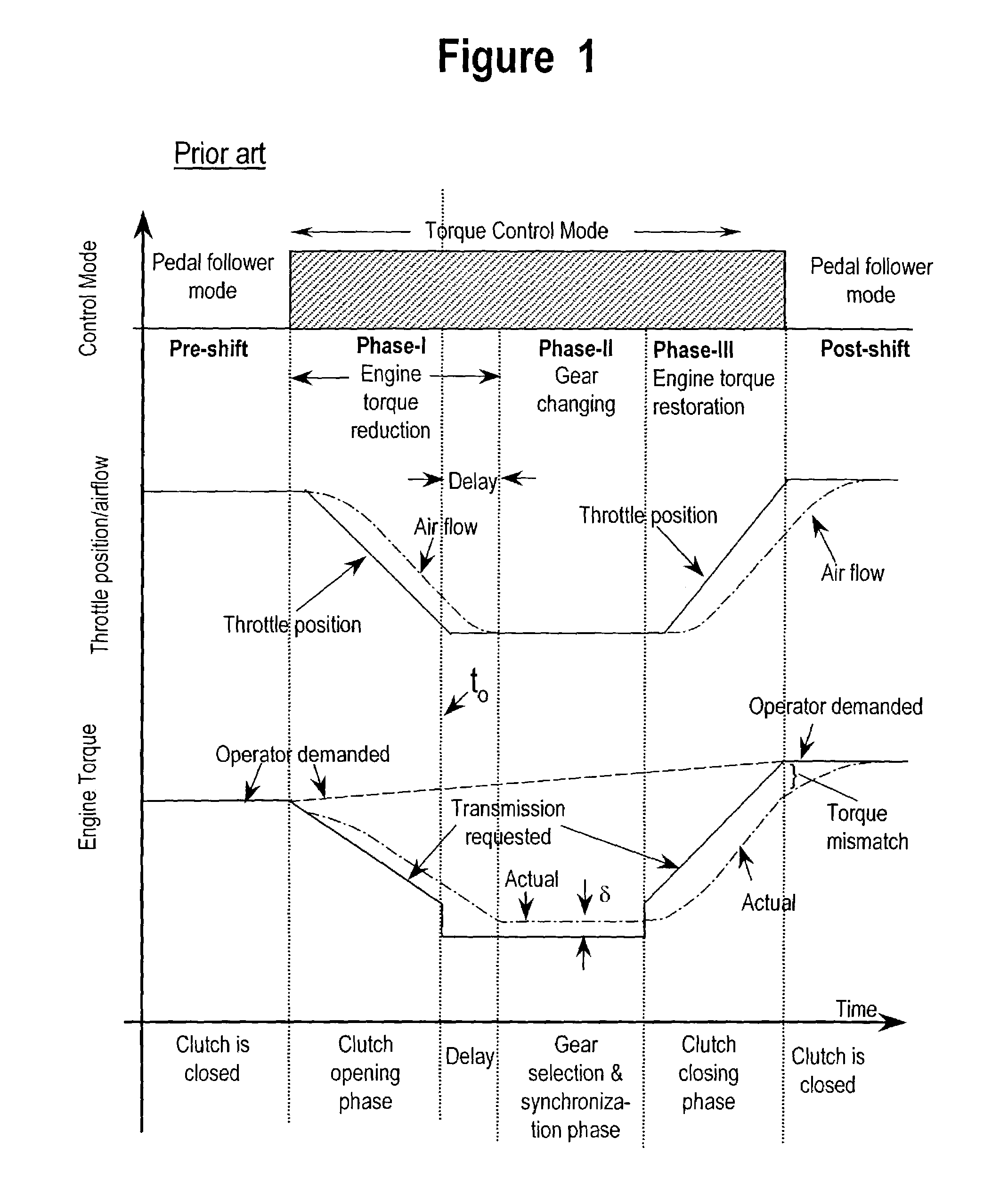
However, unlike spark timing, which is a fast actuator in which the effect of making the change occurs in the next engine firing, the effect of reducing airflow is delayed from the throttle valve actuation.
There is a slight actuator delay due to physical limitations of moving the throttle valve, i.e., there is a delay from the time that the signal is received by the throttle valve actuator and the throttle valve assumed the commanded position.
A more significant delay is the manifold emptying delay that delays the change in airflow.
However, the actual torque exceeds transmission requested torque by more than a tolerable margin.
However, the throttle valve is adjusted based on error in transmission requested torque and actual torque.
Furthermore, there are both and actuator delay, i.e., a delay from the time that the throttle is commanded to open and when it opens, and an aerodynamic delay, i.e., a manifold filling delay in which the intake manifold takes time to attain the new requested pressure and a delay due to the air accelerating to the new airflow condition.
The clutch is fully closed and the torque mismatch causes engine speed to falter.

Method used


Image

  • Method for managing engine torque during a gear shift in an automatic shift manual transmission
  • Method for managing engine torque during a gear shift in an automatic shift manual transmission
  • Method for managing engine torque during a gear shift in an automatic shift manual transmission

Examples


Embodiment Construction

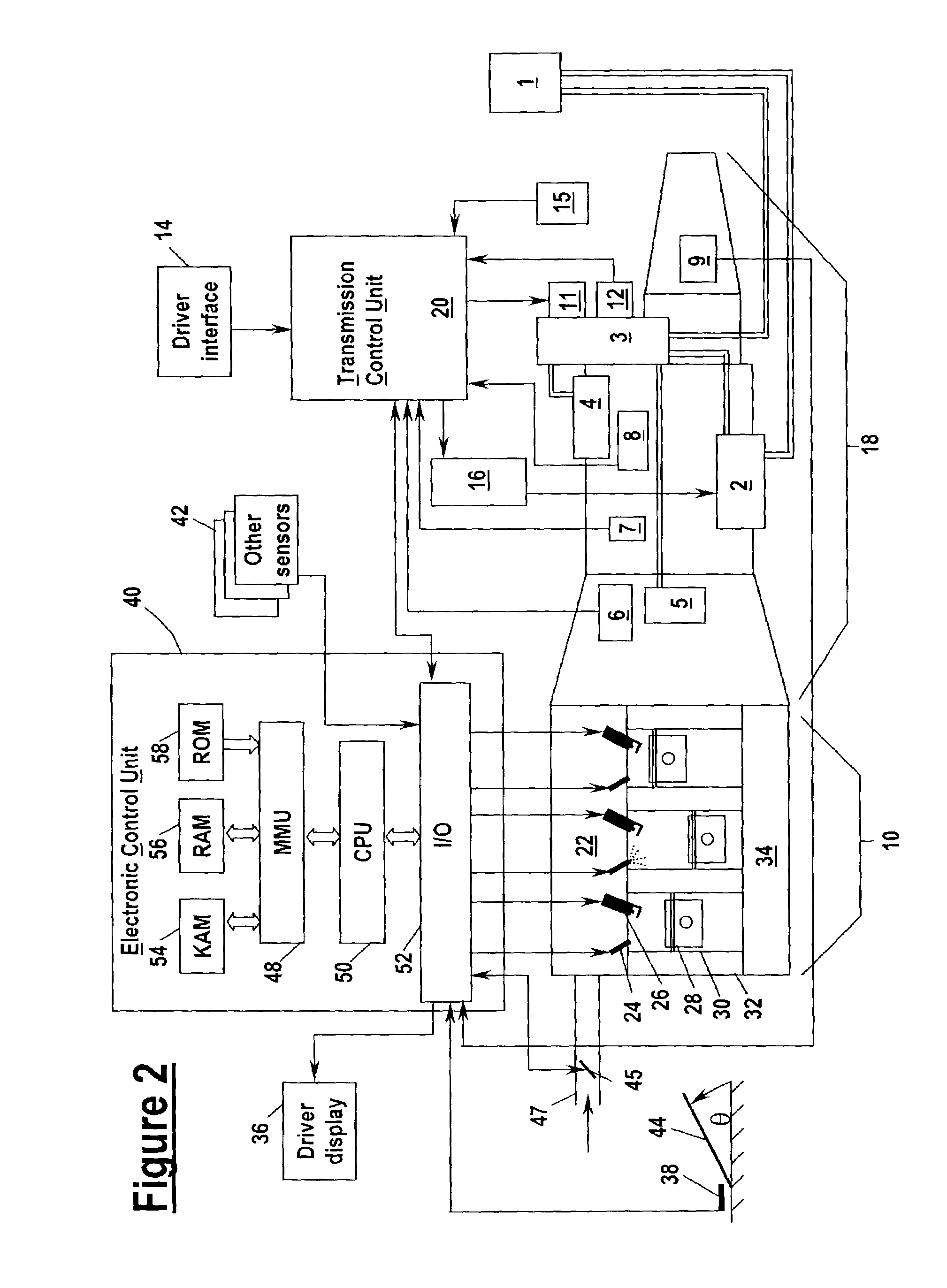
[0033]Referring to FIG. 2, an engine 10 is shown coupled and an automatic shift manual (ASM) transmission 18. The ASM transmission 18 is hydraulically actuated. The hydraulic fluid reservoir 1 is connected by hydraulic lines to an electrically-actuated hydraulic pump 2 and shift actuator 3. Shift actuator 3 is connected by hydraulic lines to clutch actuator 5 (i.e., a clutch) and a pressure accumulator 4. Hydraulic pump 2 is coupled to transmission control unit (TCU) 20 via a pump relay 16. TCU 20 receives input from clutch position sensor 6, input shaft speed sensor 7, two gear position sensors 8, output shaft speed sensor 9, pressure sensor 12, driver interface 14, and crank interrupt relay 15. Transmission control unit 20 is coupled to an engine control unit (ECU) 40 by a computer area network (CAN) connection, or other protocol capable of transferring data between the two control units, e.g., hardwired or wireless. TCU 20 controls four solenoid valves 11 which direct high pressu...


PUM


Abstract

A method and system for controlling output torque of an internal combustion engine during a gearshift in an automatic shift manual transmission coupled to the engine is disclosed. The transmission includes a multiplicity of gears and a clutch actuated by a transmission control unit (TCU), which controls clutch disengagement, gear change, and clutch re-engagement. The engine includes an engine control unit in communication with the TCU. The method includes determining engine operator demanded engine torque; sending a signal to the engine control unit in response to actuation of the clutch; and, computing in the engine control unit in response to the sent clutch actuation signal and the determined engine operator demanded engine torque, a control signal for the engine, such engine, in response to such control signal changing engine torque during the gear change to substantially match demanded engine torque when the clutch is re-engaged.

Description

FIELD OF INVENTION[0001]The present invention relates to a system and a method for managing engine torque during gear changes in an engine equipped with an automatic shift manual transmission wherein driver requested gear changes are performed by high-speed electro-hydraulic linkages.BACKGROUND OF THE INVENTION[0002]As is known in the art, with a vehicle equipped with a manual transmission, during a typical, driver-actuated gearshift event, the driver himself / herself matches the torque during the phases of the shift by adjusting the accelerator pedal position. The pedal position actuates either mechanically or electronically, the intake throttle valve.[0003]As is also known in the art, with an Automatic Shift Manual (ASM) transmission the traditional manual gearshift lever is replaced with operator hand-operated up-shift and down-shift paddles which are part of a driver interface. The ASM transmission uses a sophisticated electromechanical control system to eliminate clutch pedal co...

Claims


Application Information

Patent Timeline
IPC IPC(8): F16H59/74B60W10/02B60W10/10B60W10/11B60W30/19F02D41/02F02D41/14F02P5/02F02P5/152F16H61/04F16H63/50
CPCB60W10/11B60W30/19F02D41/023F16H61/0437F16H63/502B60W10/02B60K2741/286Y10T477/677B60W2540/10B60W2710/0605B60W2710/0666F02D41/022F02D41/1497F02P5/02F02P5/1521F16H61/682F16H2306/42Y10T477/675Y10T477/674Y10T477/669Y10T477/67B60W10/06B60W10/10
Inventor BADILLO, EDWARDKUE, ACE K.OSHINSKY, DAVIDFARMER, DAVID GEORGEDICKISON, DONALD FENWICK
Owner FORD GLOBAL TECH LLC
Learn More