Circulating grinding plant comprising a mill and a sifter

a technology of circulating grinding and milling machine, which is applied in the direction of sorting, cocoa, solid separation, etc., can solve the problems and achieve the effect of saving investment expenses, operating expenses and spa

Inactive Publication Date: 2007-11-27
KHD HUMBOLDT WEDAG GMBH
View PDF5 Cites 7 Cited by
  • Summary
  • Abstract
  • Description
  • Claims
  • Application Information

AI Technical Summary

Benefits of technology

[0005]In the case of the invention's circulating grinding plant with roller press and sifter device, at least one static cascade sifter is disposed beneath the gap of the roller press, said cascade sifter which simultaneously deagglomerates and sifts the scab material coming from the roller press. A static or in particular a dynamic subsequent sifter is arranged above the roller press, in the case of the latter named sifter type at least one rotatably arranged rod basket of a dynamic rod basket sifter provided with turbo elements on the rotor periphery for subsequent sifting of the grinding product directed through the circuit. The gritty material separated by the subsequent sifter, e.g., rod basket sifter is re-circulated by means of a penstock as a result of gravitational effect for material feed of the roller press. The sifting product discharge area of the static cascade sifter is not transported by means of a mechanical conveying agent such as e.g. a bucket conveyor, but rather is pneumatically conveyed through an ascending duct to the sifting air and sifting product inlet of the subsequent sifter, in particular dynamic rod basket sifter. As an ideal, 100% of the product of the circulating grinding plant is pneumatically conveyed through the ascending duct from the static cascade sifter up to the subsequent sifter. This solution saves investment expenses, operating expenses and space for the installation of an otherwise necessary mechanical conveying agent such as a bucket conveyor.

Problems solved by technology

This solution saves investment expenses, operating expenses and space for the installation of an otherwise necessary mechanical conveying agent such as a bucket conveyor.

Method used


Image

  • Circulating grinding plant comprising a mill and a sifter
  • Circulating grinding plant comprising a mill and a sifter

Examples


Embodiment Construction

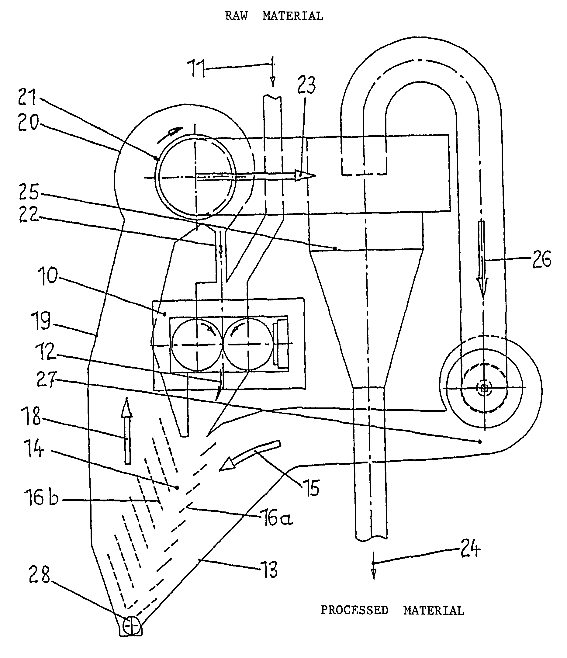
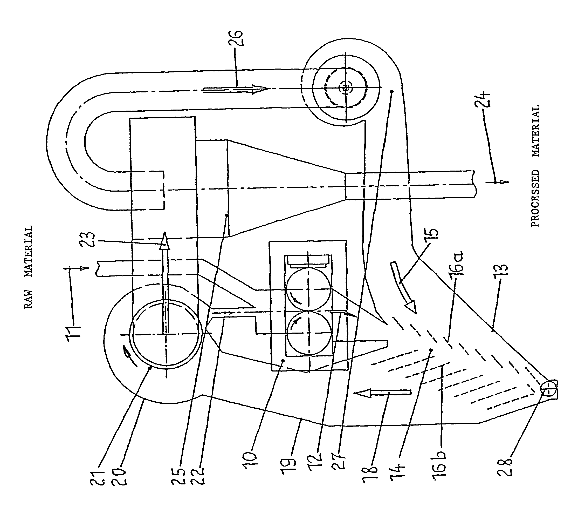
[0008]The drawing shows a compact circulating grinding plant with a product bed comminution roller mill or roller press 10 comprising a pair of opposed rollers forming a gap therebetween and with a sifter device 13. Raw material 11 that is to be ground is fed into the feed well of the roller press 10. The grinding product exits the gap pulverized and partially agglomerated, i.e., pressed into scabs 12, whose percentage of particles already reduced to the desired cement fineness can be relatively high, e.g., 30% smaller than 90 μm.

[0009]A static cascade sifter 13 is arranged below the gap of the roller press 10, with the scab material 12 being directed into the cascade sifter's product feed opening from above. The cascade sifter 13 exhibits a v-shaped shaft-shaped case with two sifting zone boundary partitions enclosed by the sifter case and forming a sifting zone 14 between them and which have sifting air 15 (or hot gas as a drying gas in the case of damp feed material) flowing thro...


PUM


Abstract

The aim of the invention is to create a compact circulating grinding plant comprising a product bed comminution roller mill or roller press and a sifter device, in which the problem of mechanically transporting the grinding product that is directed through the circuit is minimized. Said aim is achieved by a circulating grinding plant in which a static cascade sifter is disposed below the gap of the roller press while a subsequent sifter, particularly a dynamic rod basket sifter, is disposed above said roller press. The sifting product discharge area of the static cascade sifter is connected to the sifting air and sifting product inlet of the subsequent sifter via an ascending duct which pneumatically conveys the product.

Description

BACKGROUND OF THE INVENTION[0001]The invention relates to a circulating grinding plant for the grinding of raw material, with a high-pressure roller mill or roller press with product bed comminution of the feed material and with a sifter device, comprising a static cascade sifter, to which at least one additional sifter is subsequently added on the sifting air current side, whose oversize material discharge is connected to the material feed of the roller press.[0002]Pressure comminution of granular grinding product in the gap between two press rollers is known in the manner that the individual particles of the grinding product are mutually crushed upon application of a high pressure in a material bed compressed between the two roller surfaces, so that in this case one speaks of the so-called product bed comminution. The compression stress results partly in a particle destruction of the grinding product, and partly in the generation of cracks in the particle interior and manifests it...

Claims


Application Information

Patent Timeline
Patent Type & Authority Patents(United States)
IPC IPC(8): B02C23/22B02C4/02B02C23/12B02C23/14B02C23/30B02C23/34B07B4/02B07B4/04B07B9/02
CPCB02C4/02B02C23/12B02C23/14B07B9/02B02C23/34B07B4/02B07B4/04B02C23/30
Inventor HAGEDORN, ALEXANDERFISCHER-HELWIG, FRANKSPLINTER, CHRISTIANFRANGENBERG, MEINHARD
Owner KHD HUMBOLDT WEDAG GMBH
Why Eureka
Try Eureka