
Recovery of calibrated center steering position after loss of battery power

a center steering position and battery power technology, applied in the direction of non-deflectable wheel steering, underwater vessels, special data processing applications, etc., can solve the problems of inaccurate count, insufficient angular resolution for any associated control system, ambiguous absolute steering angle, etc., and achieve accurate absolute steering angle

Active Publication Date: 2007-11-13
TRW AUTOMOTIVE US LLC
View PDF25 Cites 1319 Cited by
  • Summary
  • Abstract
  • Description
  • Claims
  • Application Information

AI Technical Summary

Benefits of technology

[0015]The present invention has the advantage of maintaining an accurate absolute steering angle without requiring a reference position sensor to provide an index marker signal. In addition, the present invention avoids the need for any high resolution sensor outside of the EPAS electric motor.
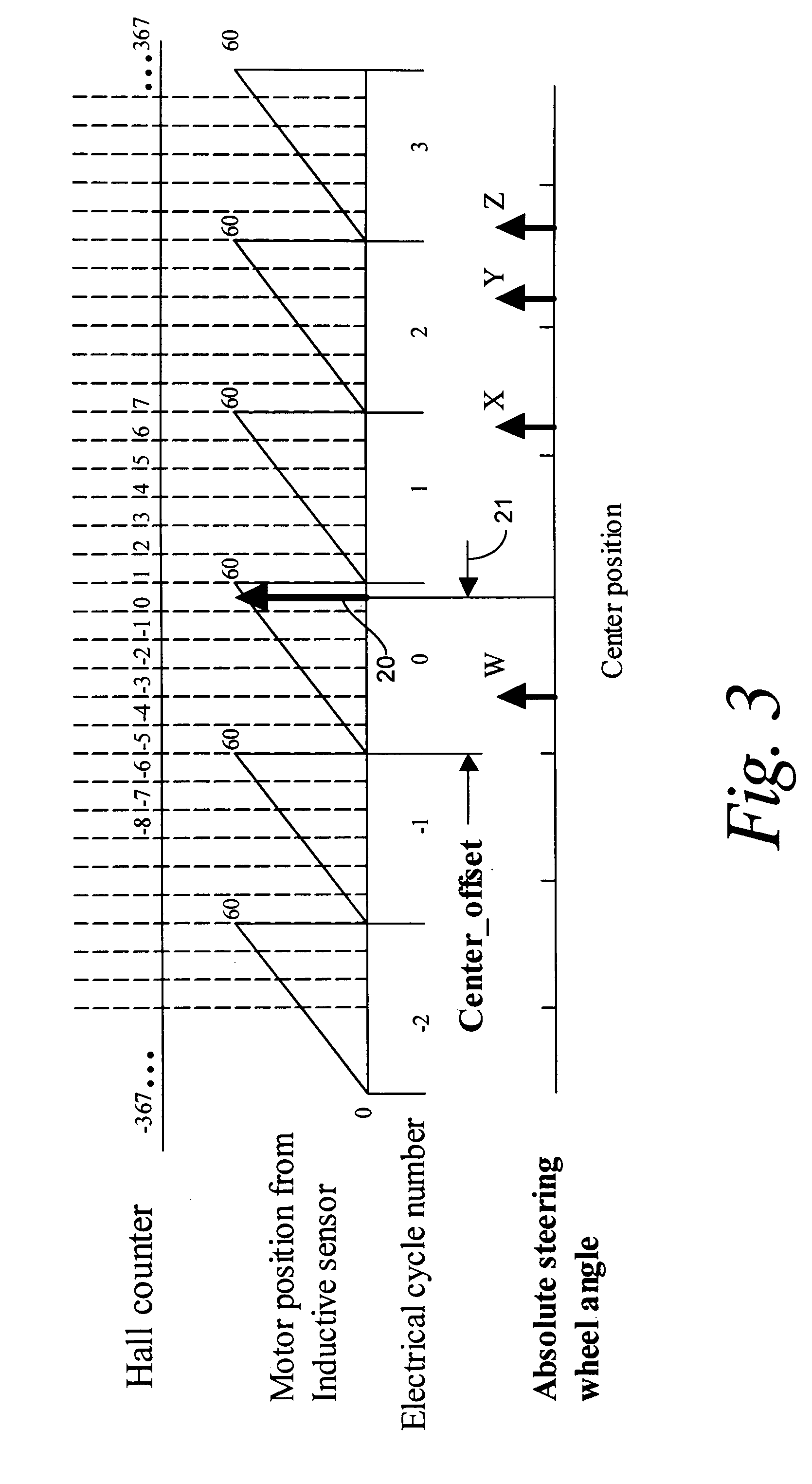
[0016]An inductive sensor (or other resolver) within the electric motor (e.g., having an angular resolution of about 60 resolved positions within each electrical cycle of the motor) is combined with a Hall-effect sensor on the electric motor having a measuring range greater than one electrical cycle (but not necessarily a full mechanical rotation). A factory calibrated center steering position (in terms of the state of the Hall-effect sensor and an inductive sensor position counter) is stored by an EPAS controller. By counting both the Hall-state transitions and the inductive sensor pulses relative to the stored center position, a sufficiently accurate steering angle can be maintained.

Problems solved by technology

However, this measurement alone is not sufficient for use as an indication of the position of the steering angle because 1) the electric motor goes through many complete electrical cycles as the steering system passes through its full range of motion, so the motor position output will repeat at different steering angles and thus produce an ambiguous signal (just as a steering shaft position sensor does), and 2) the angular resolution may be inadequate for any associated control systems using steering angle as an input (e.g., a vehicle stability control system).
In addition, the steering angle may be changed while the ignition is off, resulting in an inaccurate count unless the sensor continues to be monitored.
In the event of a dead main battery or other loss of power to the EPAS system, the latched value of the Hall counter may be lost, resulting in ambiguity of the absolute steering angle.
This produces an output which does not depend on the EPAS gearbox ratio since it reads directly from the steering shaft, but is expensive to produce.
The resolution obtainable with Hall-effect sensors of reasonable cost may be insufficient for some motor control purposes.
However, there are typically several electrical cycles within one full mechanical rotation of the rotor, so that the position derived from the inductive sensor is ambiguous with respect to the mechanical position.

Method used


Image

  • Recovery of calibrated center steering position after loss of battery power
  • Recovery of calibrated center steering position after loss of battery power
  • Recovery of calibrated center steering position after loss of battery power

Examples


Embodiment Construction

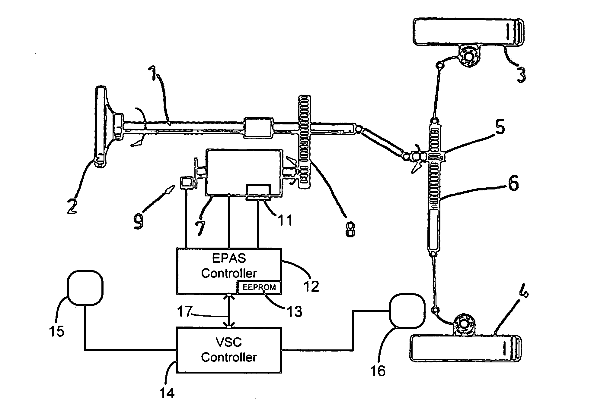
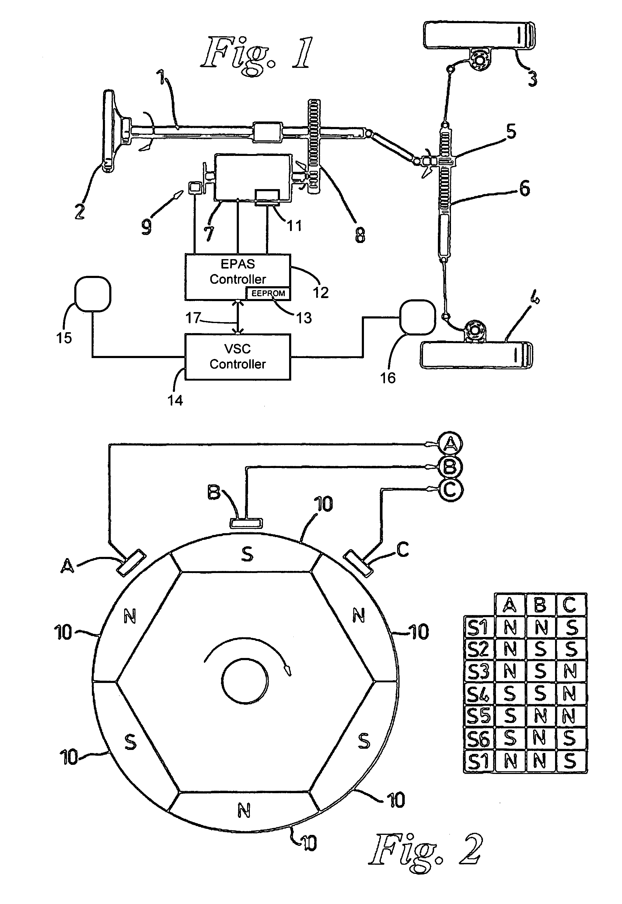
[0026]Referring now to FIG. 1, a steering shaft 1 is operatively connected at one end to a steering wheel 2 and at its opposing end to a pair of road wheels 3 and 4 through a rack and pinion gearbox 5 and 6. In order to provide torque assistance to the driver, the system further includes an electric motor 7 connected to the steering shaft 1 through a reduction gearbox 8. Motor 7 may, for example, comprise a 3-phase permanent magnet brushless motor with a sensing means 9 comprising three Hall effect sensors A, B, and C arranged around the motor 7 to detect the electrical angle of the rotor by measuring the position of rotor magnets 10. The spacing of Hall effect sensors A, B, and C and the number of north / south magnet pairs deployed around the circumference must be sufficiently numerous to differentiate between different electrical cycles of motor 7 within 360° of mechanical rotation.

[0027]Motor 7 further includes an inductive position sensor 11 for measuring rotor position within on...


PUM


Abstract

The steering angle of a vehicle is monitored using position sensors of an electric motor of an electric power assisted steering (EPAS) system. A position of the electric motor corresponding to the straight-ahead, center position of the steering system is stored in non-volatile memory during a steering calibration procedure, such as an end-of-line calibration in a vehicle assembly plant. Following power loss due to a dead battery, a steering angle zeroing procedure performed in a vehicle stability control (VSC) system generates a center position with enough accuracy to be within one electrical cycle of the motor. The pre-stored electric motor position is then used to determine the electrical cycle where the center position was located, and accurate monitoring of steering angle is resumed.

Description

CROSS REFERENCE TO RELATED APPLICATIONS[0001]Not applicable.STATEMENT REGARDING FEDERALLY SPONSORED RESEARCH[0002]Not Applicable.BACKGROUND OF THE INVENTION[0003]The present invention relates in general to maintaining an accurate steering angle position relative to a center steering angle of a motor vehicle, and more specifically to electric power assisted steering systems for vehicles wherein an electric motor operatively connected to a steering assembly includes position sensors for assisting in the determination of the steering angle.[0004]It is well known to provide electric power assisted steering (EPAS) systems. A steering assembly typically comprises a hand wheel connected to a steering shaft which is operatively connected to one or more road wheels through a steering rack, although many different assemblies are in common use. Some EPAS systems use brushless electric motors with a motor position sensor to control the timing of switching (i.e., commutation of windings of the m...

Claims


Application Information

Patent Timeline
Patent Type & Authority Patents(United States)
IPC IPC(8): B62D6/00
CPCB62D15/0245B62D15/0235
Inventor LU, ENGELBERTMCLAUGHLIN, KEVIN
Owner TRW AUTOMOTIVE US LLC
Learn More