
Beam shaping element, and light source unit and optical pickup using same

Inactive Publication Date: 2007-11-13
SHARP KK
View PDF11 Cites 5 Cited by
  • Summary
  • Abstract
  • Description
  • Claims
  • Application Information

AI Technical Summary

Benefits of technology

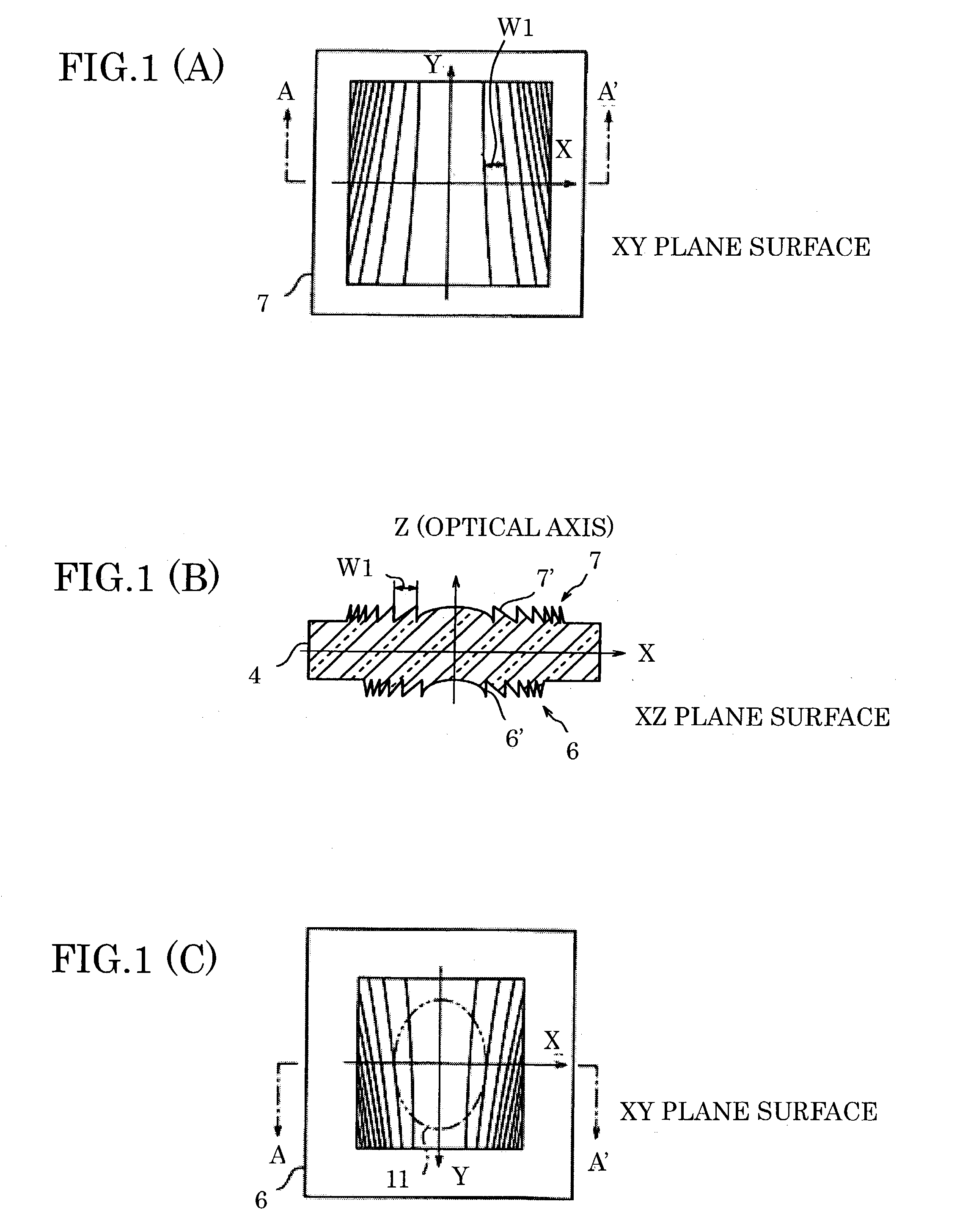
[0009]In light of the conventional problems above, an object of the present invention is to provide a beam shaping element that enables to correct displacement of a light emitting point of a light source simply by performing positional adjustment in the plane vertical to an optical axis, thereby making it unnecessary to perform positional adjustment along an optical axis direction and to provide a light source unit and an optical pickup using the beam shaping element.
[0011]According to the arrangement above, it is possible to provide the beam shaping element that enables to correct the displacement of the light emitting point of the light source simply by performing positional adjustment in the plane vertical to the optical axis, thereby making it unnecessary to perform positional adjustment along the optical axis direction.
[0014]According to the arrangement above, it is more easy to correct the displacement of the light emitting point of the light source that emits the light beam can more easily be corrected.
[0016]According to the method above, it is possible to provide the positional adjustment method that enables to correct the displacement of the light emitting point of the light source simply by performing positional adjustment of the light source and the beam shaping element within the surface, thereby making it unnecessary to adjust distance between the light source and the beam shaping element.
[0018]According to the arrangement above, it is possible to provide the light source unit which is easy to assemble and highly reliable.
[0020]According to the arrangement above, it is possible to collect the light beam radiated from the light source by the collimating means as a spot having a substantially round shape, and to provide the optical pickup that does not require a moving mechanism for moving the beam shaping element or the light source along the optical axis direction in order to correct the displacement of the light source.

Problems solved by technology

Therefore, light volume of the light beam cannot be efficiently used if the light beam is condensed directly, because the light beam makes an elliptical shape spot when the light beam is condensed directly.
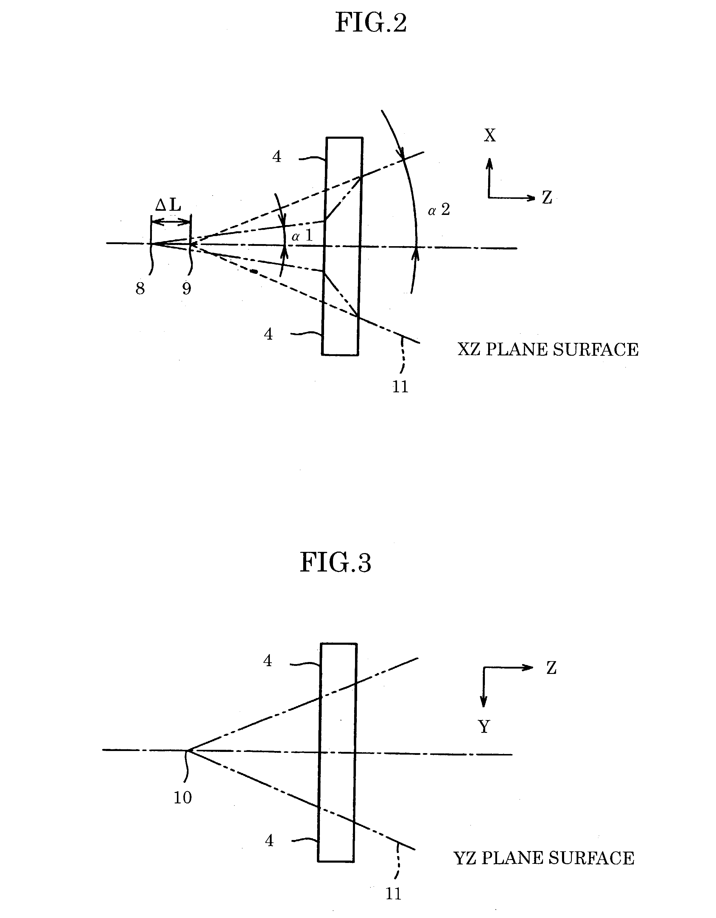
Moreover, a focal point in the horizontal direction and a focal point in the vertical direction do not match if the light beam is condensed directly, because positions of a light emitting point are actually different (displacement of an actual light emitting point).
According to the arrangement above, however, there is a problem that an optical pickup as a whole becomes large because a size of the shaping prism 18 cannot be sufficiently reduced, and because at least two shaping prisms 18 must be used in order to keep the optical path of the light beam 11 parallel before and after the light beam 11 is shaped.
Moreover, it is necessary to adjust distance between the shaping element 19 and the semiconductor laser in accordance with property of each semiconductor laser because each semiconductor laser produced has different wavelength and amount of displacement of the actual light emitting point, thereby causing inter-individual errors (inter-individual unevenness).
In short, for example, when a combination of the shaping element 19 and the semiconductor laser element (e.g. the optical pickup) is used, there is a problem that time and costs for the positional adjustment in the optical axis direction are needed irrespective of whether or not the shaping element 19 and the semiconductor laser element are unitized.

Method used


Image

  • Beam shaping element, and light source unit and optical pickup using same
  • Beam shaping element, and light source unit and optical pickup using same
  • Beam shaping element, and light source unit and optical pickup using same

Examples


examples

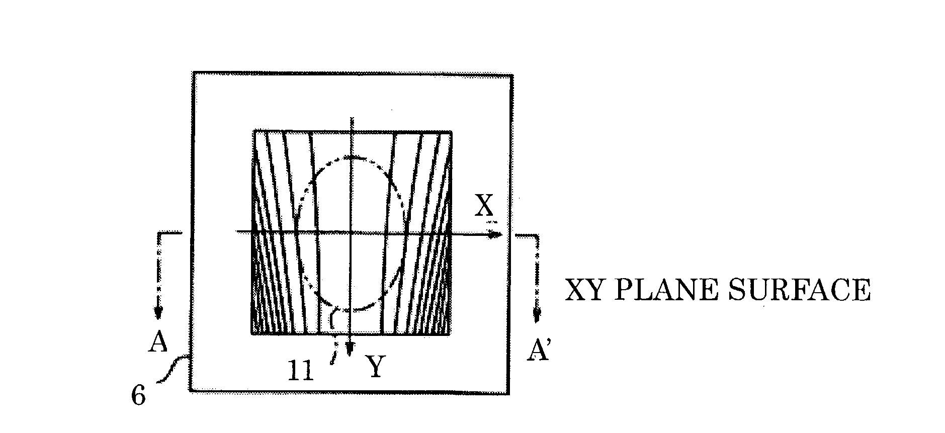
[0138]The following describes, by explaining examples, specific design examples of the beam shaping element 4 described in the embodiment.

[0139]In the optical pickup 1 shown in FIG. 6, the light beam 11 of the semiconductor laser 3 had a central wavelength of 405 nm. The light beam 11 of the semiconductor laser 3 had different radiation angles in horizontal and vertical directions: full angle at half maximum (half of the radiation angle) in the direction horizontal with respect to a composition surface of the semiconductor laser 3 was 10 degrees, and full angle at half maximum (half of the radiation angle) in the direction vertical with respect to the composition surface of the semiconductor laser 3 was 26 degrees, whereby the light beam 11 of the semiconductor laser 3 had a substantially elliptical shape. The light beam 11 was shaped into a substantially round shape by expanding the radiation angle in the shaping direction (the horizontal direction). Then, the light beam was suffic...


PUM


Abstract

A beam shaping element includes a set of diffraction gratings on each surface thereof, in such a manner that intervals between the gratings farer from a vicinity of an optical axis and nearer to a periphery are narrower, wherein each interval between the respective gratings monotonously increases or monotonously decreases along a direction in which each grating-shaped pattern extends. According to the arrangement above, it is possible to correct displacement of a light emitting point of a light source by simply performing a positional adjustment within a plane that is orthogonal to the optical axis. Thus, it is possible to provide the beam shaping element that enables to correct the displacement of the light emitting point of the light source simply by performing positional adjustment in the plane vertical to the optical axis, thereby making it unnecessary to perform positional adjustment along the optical axis direction, and to provide a light source unit and an optical pickup using the beam shaping element.

Description

FIELD OF THE INVENTION[0001]The present invention relates to a beam shaping element for shaping a light beam having an elliptical shape cross-section into a substantially round shape, and a light source unit and an optical pickup including the beam shaping element.BACKGROUND OF THE INVENTION[0002]Information storage mediums such as optical disks have been improved to have high density so as to attain larger storage capacity. In order to realize high density in a disk-shaped information storage medium such as an optical disk, it is necessary to reduce a spot diameter of a light beam condensed onto the optical disk. However, a light beam is radiated from a semiconductor laser element, which is typically used as a light source, in such a manner that a radiation angle in a direction vertical to a composition surface of a laser chip (vertical direction) and a radiation angle in a direction horizontal to the composition surface of the laser chip (horizontal direction) are different. The r...

Claims


Application Information

Patent Timeline
IPC IPC(8): G11B7/00G02B5/18G02B27/09G11B7/135G11B7/1353G11B7/1392G11B7/1398
CPCG11B7/1353G11B7/1398G11B7/13922
Inventor KITAZAWA, TAZUKOIWAKI, TETSUO
Owner SHARP KK
Learn More