
Coordinate measuring machine

a technology of measuring machine and coordinate, which is applied in the direction of mechanical measuring arrangement, instruments, and using mechanical means, etc., can solve the problems of increasing measurement error, reducing the time required for correction processing, and reducing measurement error

Active Publication Date: 2012-07-24
MITUTOYO CORP
View PDF3 Cites 21 Cited by
  • Summary
  • Abstract
  • Description
  • Claims
  • Application Information

AI Technical Summary

Benefits of technology

[0016]An object of the invention is to provide a coordinate measuring machine that can properly correct a displacement of a probe irrespective of a change in a measurement condition and can reduce a measurement error.

Problems solved by technology

Here, an error between the displacement of the probe acquired by the surface profile measuring instrument and actual displacement of the probe inevitably results in an error in the measurement value.
However, when the displacement of the probe is corrected by the predetermined correction parameters, the coordinate measuring machine may not properly correct the displacement of the probe under a measurement condition different from that when the correction parameters are obtained, thus resulting in increase in the measurement error.
On the other hand, when the measurement conditions during the probe calibration and the profiling measurement are different, as shown in FIGS. 8B and 8C and FIGS. 9B and 9C, the coordinate measuring machine cannot appropriately correct the displacement of the probe and the measurement error is enlarged.

Method used


Image

  • Coordinate measuring machine
  • Coordinate measuring machine
  • Coordinate measuring machine

Examples


Embodiment Construction

)

[0052]An exemplary embodiment of the invention will be described below with reference to the attached drawings.

Outline of Coordinate Measuring Machine

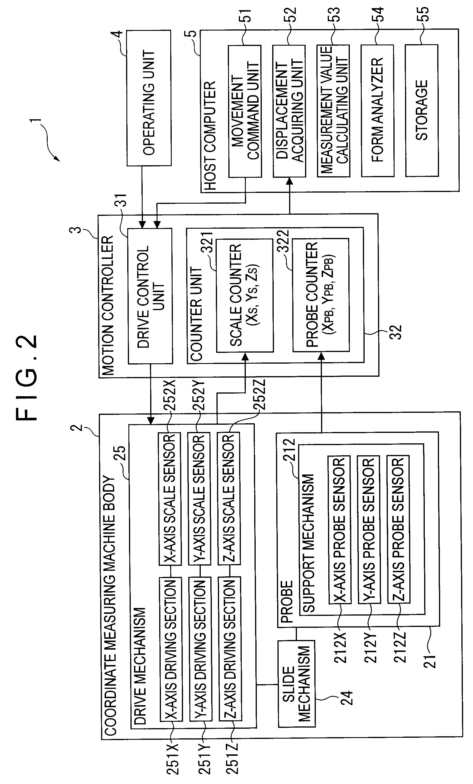
[0053]FIG. 1 is a view showing an entirety of a coordinate measuring machine 1 according to the exemplary embodiment of the invention. FIG. 2 is a block diagram showing an outline of the coordinate measuring machine 1. An upper direction in FIG. 1 is denoted as +Z-axis direction and two axes perpendicular to the Z-axis are respectively denoted as an X-axis and Y-axis, which also applies in the rest of the drawings.

[0054]As shown in FIG. 1, the coordinate measuring machine 1 includes: a coordinate measuring machine body 2; a motion controller 3 that controls the drive of the coordinate measuring machine body 2; an operating unit 4 that issues a command to the motion controller 3 via an operation lever and the like to manually operate the coordinate measuring machine body 2; a host computer 5 that issues a predetermined command to the m...


PUM


Abstract

A coordinate measuring machine includes: a probe that has a contact point capable of movement within a predetermined range; a movement mechanism for moving the probe; and a controller for controlling the movement mechanism. The controller has a measurement value calculating unit for calculating a position of the contact point based on a displacement of the movement mechanism and a displacement of the probe. The measurement value calculating unit includes: a correction parameter calculator for calculating a correction parameter for correcting the displacement of the probe based on a measurement condition in measuring an object; a corrector for correcting the displacement of the probe based on the correction parameter; and a displacement synthesizing unit that synthesizes the displacement of the movement mechanism and the displacement of the probe corrected by the corrector to calculate the position of the contact point.

Description

[0001]The entire disclosure of Japanese Patent Application No. 2009-000675, filed Jan. 6, 2009, is expressly incorporated by reference herein.BACKGROUND OF THE INVENTION[0002]1. Field of the Invention[0003]The present invention relates to a coordinate measuring machine.[0004]2. Description of Related Art[0005]Typically known coordinate measuring machine includes: a probe that is adapted to move within a predetermined range, the probe having a contact point to be in contact with an object to be measured; a movement mechanism that holds and moves the probe; and a controller that controls the movement mechanism. The coordinate measuring machine measures the object by moving the contact point along the surface of the object to be measured while forcing the probe against the object (see, for instance, Document 1: JP-A-2008-89578).[0006]The surface profile measuring instrument (coordinate measuring machine) disclosed in the Document 1 moves the contact point along the surface of the objec...

Claims


Application Information

Patent Timeline
Patent Type & Authority Patents(United States)
IPC IPC(8): G01C17/38G01B5/008
CPCG01B21/045
Inventor NAKAGAWA, HIDEYUKIISHIKAWA, NOBUHIRO
Owner MITUTOYO CORP
Learn More