
Interleaved power converter

a power converter and integrated technology, applied in the direction of process and machine control, instrumentation, and semiconductor/solid-state device details, etc., can solve the problems of limiting the operating range, increasing cost, increasing size and/or weight,

Active Publication Date: 2007-11-13
VITESCO TECH USA LLC
View PDF56 Cites 64 Cited by
  • Summary
  • Abstract
  • Description
  • Claims
  • Application Information

AI Technical Summary

Benefits of technology

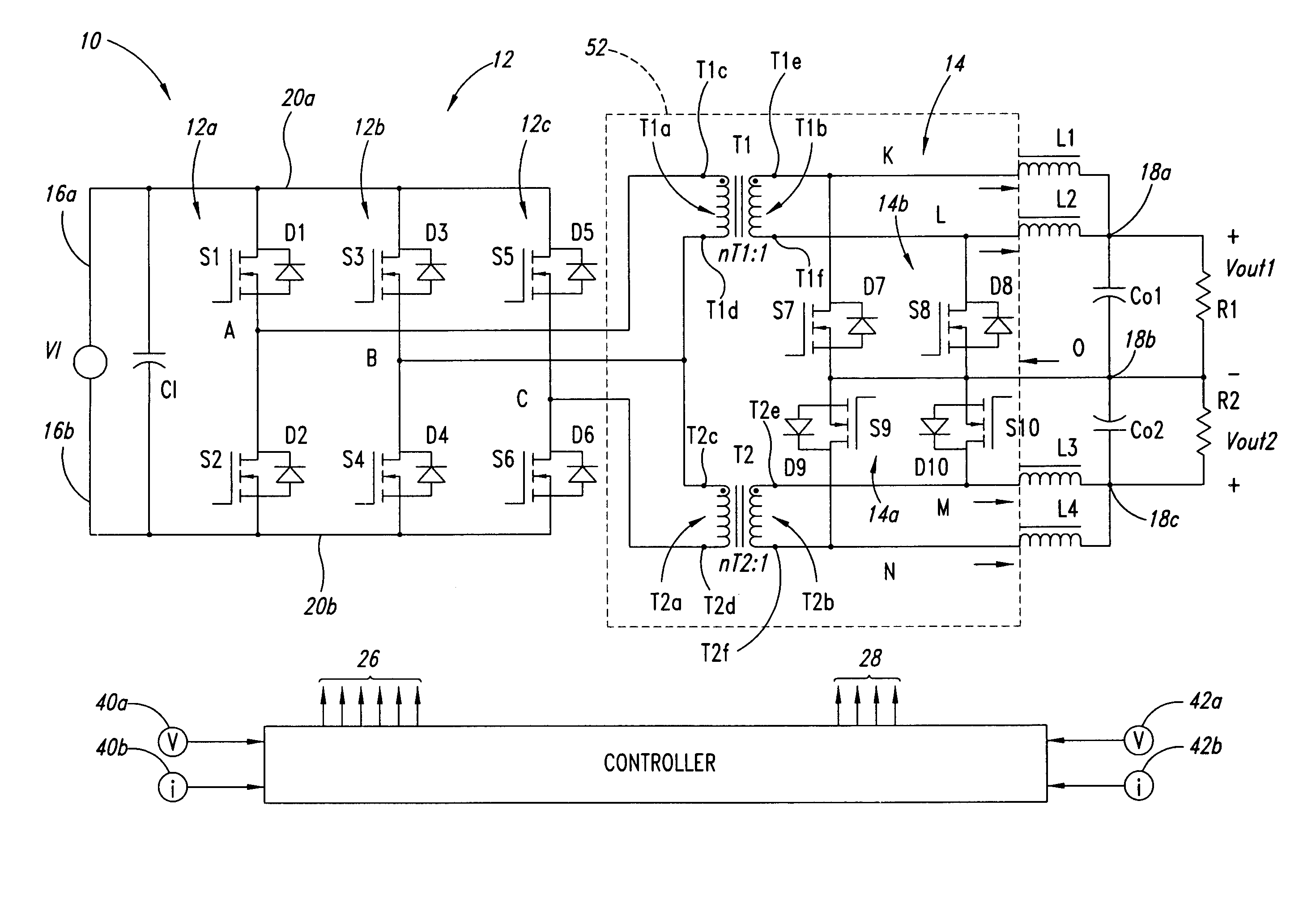
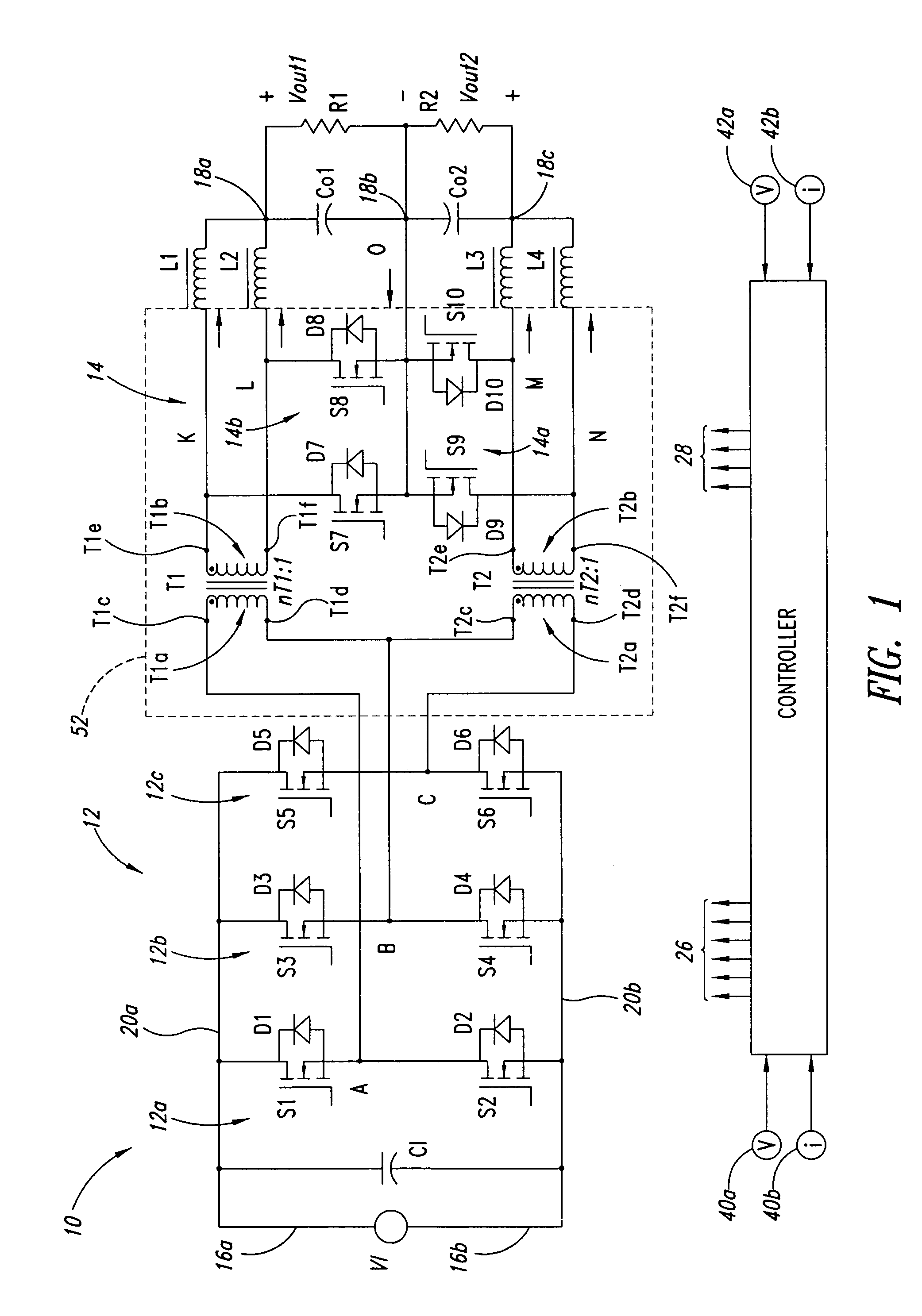
The patent describes a power converter that can efficiently convert direct current to alternating current with three phases. The converter includes an inverter circuit with three phase legs and two transformers. The first transformer is connected between the first and second phase legs, and the second transformer is connected between the first and third phase legs. The method involves supplying alternating current to the first and second transformers, and then rectifying the currents to produce voltage across different potential nodes. The technical effect of this invention is a more efficient and reliable power converter for various applications such as power conversion for electric vehicles.

Problems solved by technology

These power semiconductor devices dissipate large amounts of heat during high power operation, creating thermal management problems which may limit the operating range, increase cost, increase size and / or weight, adversely effect efficiency, and / or reduce reliability of the power converter.

Method used


Image

  • Interleaved power converter
  • Interleaved power converter
  • Interleaved power converter

Examples


Embodiment Construction

[0026]In the following description, certain specific details are set forth in order to provide a thorough understanding of various embodiments. However, one skilled in the art will understand that the invention may be practiced without these details. In other instances, well-known structures associated with power converters, controllers and / or gate drives have not been shown or described in detail to avoid unnecessarily obscuring descriptions of the embodiments.

[0027]Unless the context requires otherwise, throughout the specification and claims which follow, the word “comprise” and variations thereof, such as, “comprises” and “comprising” are to be construed in an open sense, that is as “including, but not limited to.”

[0028]Reference throughout this specification to “one embodiment” or “an embodiment” means that a particular feature, structure or characteristic described in connection with the embodiment is included in at least one embodiment. Thus, the appearances of the phrases “i...


PUM


Abstract

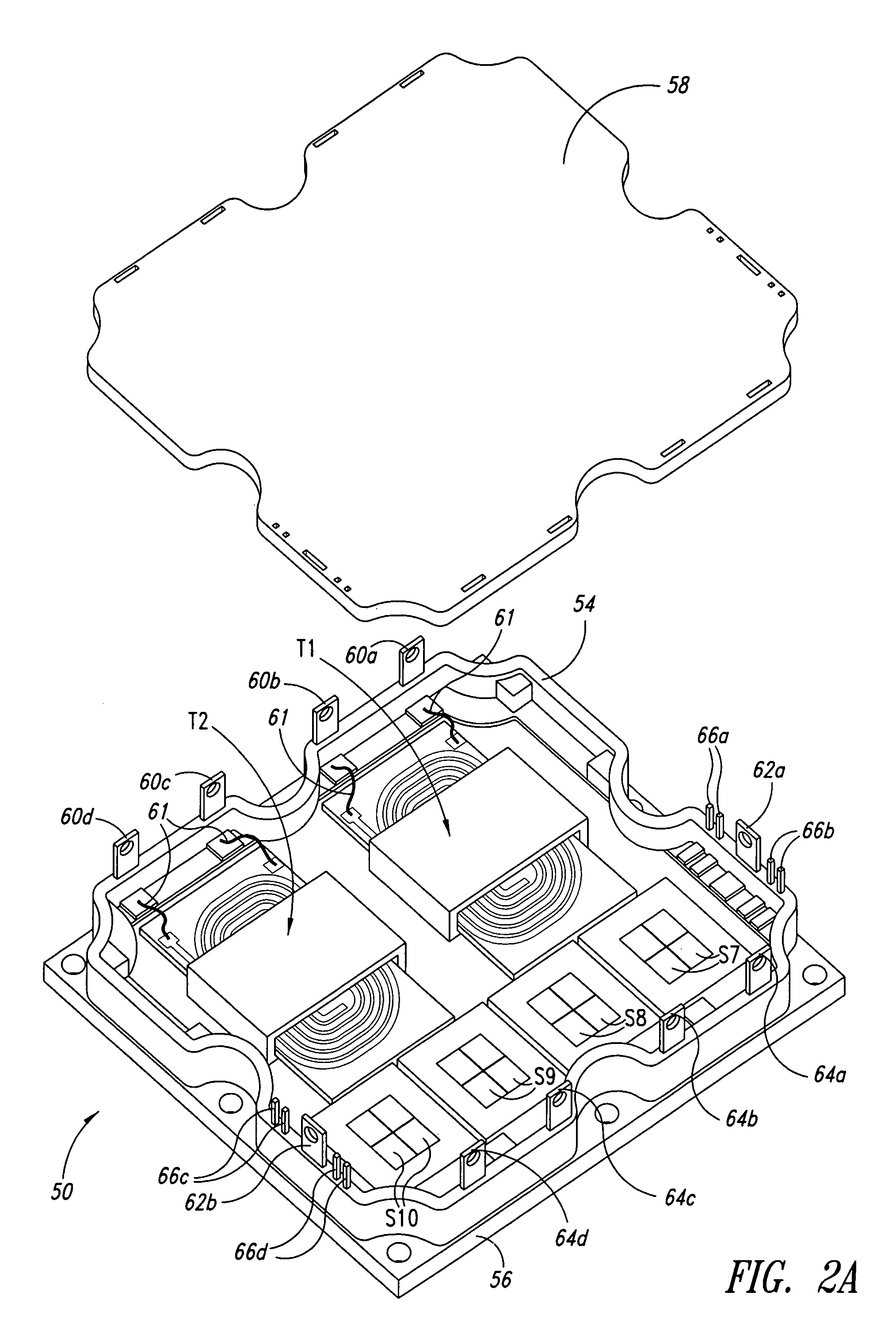
A power converter architecture interleaves full bridge converters to alleviate thermal management problems in high current applications, and may, for example, double the output power capability while reducing parts count and costs. For example, one phase of a three phase inverter is shared between two transformers, which provide power to a rectifier such as a current doubler rectifier to provide two full bridge DC / DC converters with three rather than four high voltage inverter legs.

Description

STATEMENT OF GOVERNMENT INTEREST[0001]This invention was made with government support under Subcontract No. 400029752, Prime Contract No. DE-AC05-00OR22725, awarded by the Department of Energy. The government has certain rights in this invention.BACKGROUND OF THE INVENTION[0002]1. Field of the Invention[0003]This disclosure generally relates to electrical power systems, and more particularly to power module architectures suitable for rectifying, inverting, and / or converting electrical power between power sources and loads.[0004]2. Description of the Related Art[0005]Power modules are typically self-contained units that transform and / or condition power from one or more power sources for supplying power to one or more loads. Power modules commonly referred to as “inverters” transform direct current (DC) to alternating current (AC), for use in supplying power to an AC load. Power modules commonly referred to as “rectifiers” transform AC to DC. Power modules commonly referred to as “DC / ...

Claims


Application Information

Patent Timeline
Patent Type & Authority Patents(United States)
IPC IPC(8): H02M3/335
CPCH02M3/33576H01L23/645H01L25/16H01L2924/0002H01L2924/00H02M3/335
Inventor ZHU, LIZHI
Owner VITESCO TECH USA LLC
Learn More