
Rearview video output device

a rearview and video output technology, applied in the field of rearview video output devices, can solve the problems of loss of image clarity and brightness, affecting the appearance of the vehicle, and the way mirrors tend to darken and distort, so as to enhance the reflectivity of the transparent plate, uniform background color and texture, and great reflectivity

Inactive Publication Date: 2007-11-06
SAVV
View PDF40 Cites 166 Cited by
  • Summary
  • Abstract
  • Description
  • Claims
  • Application Information

AI Technical Summary

Benefits of technology

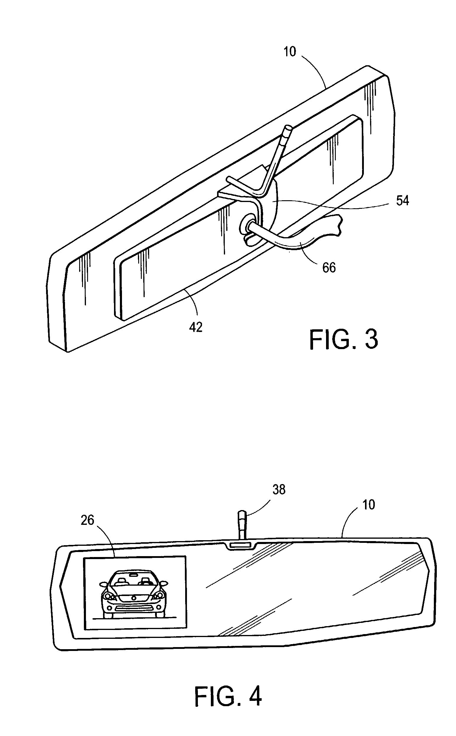
[0010]The interior background of the transparent plate is much darker than the exterior. The dark background combines with the transparent plate to make a highly reflective surface, the same way an exterior window of a darkened room has greater reflectivity that the exterior window of a brightly lit room. The reflectivity of the transparent plate in front of the video output device is eliminated when it is turned on. The images produced by the video-output device are clearly transmitted through the transparent plate while the rest of the transparent plate remains highly reflective. The transparent plate does not darken or distort the transmitted image.
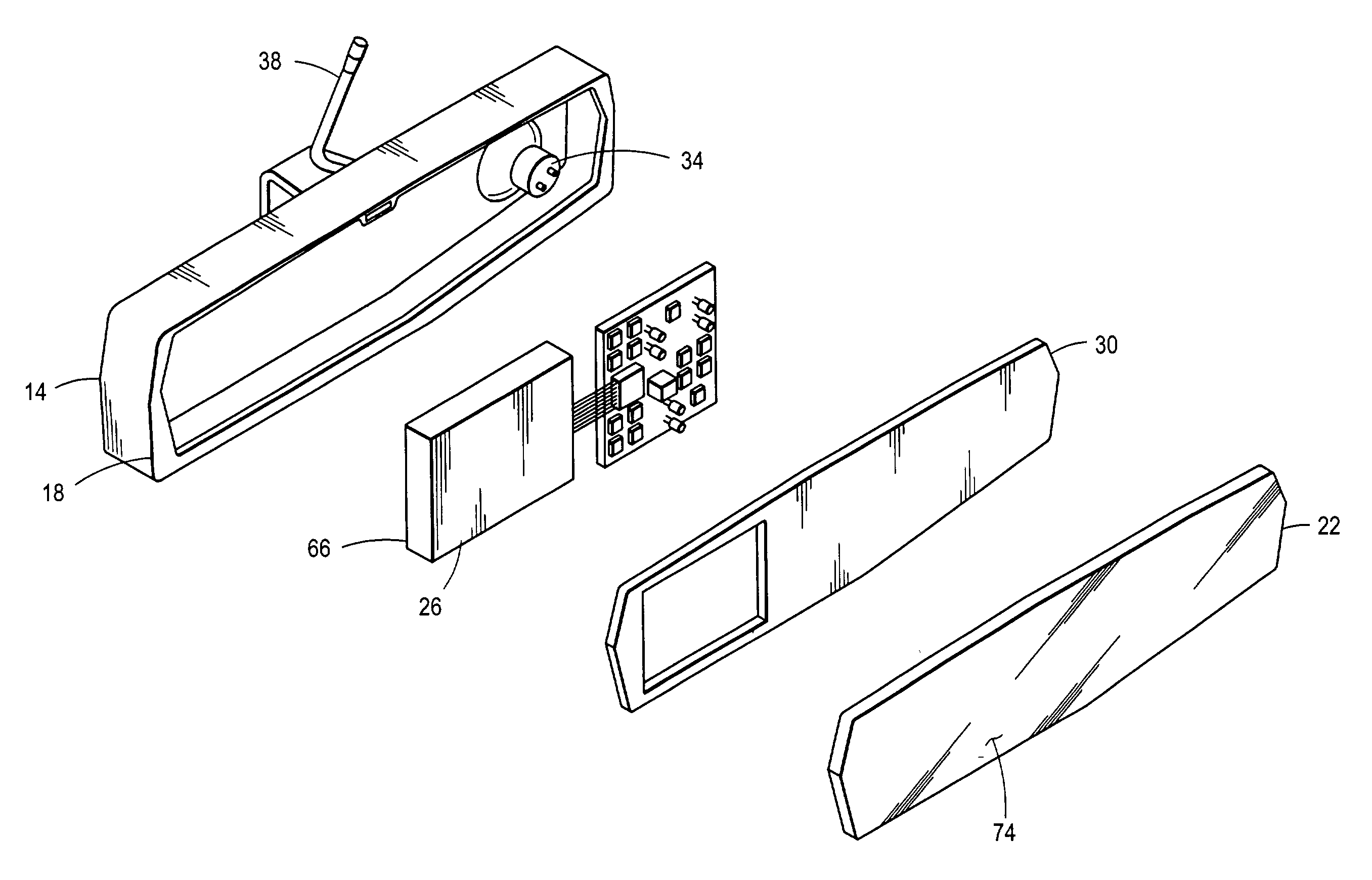
[0011]In a first variation of this invention, a sheet is located behind the transparent plate and within the cover. The sheet enhances the reflectivity of the transparent plate by providing a uniform background color and texture. The sheet is sized to permit pass through installation of each video output device.
[0019]In still another variation of this invention, the transparent plate has an anti-glare exterior surface coating. The coating diffuses and reduces the brightness of the exterior light entering the device through the transparent plate so that the video output device remains clearly visible.

Problems solved by technology

The two-way mirror tends to darken and distort video images transmitted through it.
Therefore, image clarity and brightness are lost, especially during daylight viewing.

Method used


Image

  • Rearview video output device
  • Rearview video output device
  • Rearview video output device

Examples


Embodiment Construction

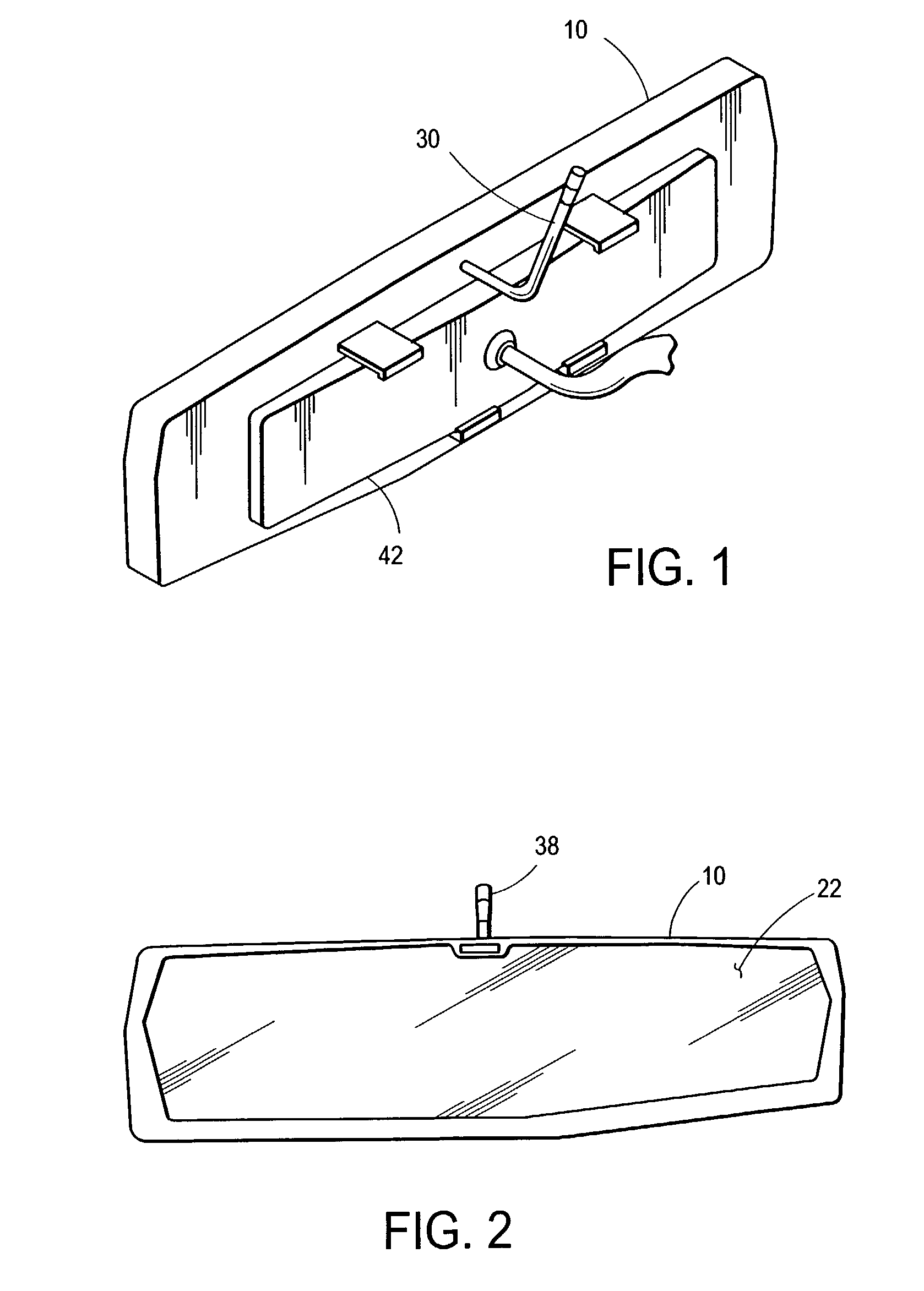
[0034]The invention resides in a rearview video-output device. As shown in FIGS. 1, 3 and 5, the rearview video-output device 10 includes a cover 14. The cover 14 has an opening on its backside 18. A transparent plate 22 is mounted into the backside opening 18 of the cover 14. At least one video output device 26 is located behind the transparent plate 22 and within the cover 14. At least one audio output device 34 is located within the cover 14. A cable 38 provides a means for inputting at least one video signal, at least one audio signal and electric power. The cable 38 can be either a 5-pin or an 8-pin DIN cable. A DIN Cable is commonly used for audio and control applications. A means for attaching the cover 14 to the center rearview mirror 42 is provided.

[0035]The interior background of the transparent plate 22 is much darker than the exterior. The dark background combines with the transparent plate 22 to make a highly reflective surface, the same way an exterior window of a dark...


PUM


Abstract

The invention is a rearview video-output device with a cover, a transparent plate mounted into the cover with at least one video output device and at least one audio output device located within the cover. A cable provides a means for inputting at least one video signal, at least one audio signal and electric power. A means for attaching the cover to the center rearview mirror is provided. A sheet is located behind the transparent plate and within the cover. The sheet enhances the reflectivity of the transparent plate by providing a uniform background color and texture. The sheet is sized to permit pass through installation of each video output device. The device does not limit video clarity and brightness. The abstract is submitted with the understanding that it will not be used to interpret or limit the scope or meaning of the claims.

Description

CROSS-REFERENCE TO RELATED APPLICATIONS[0001]Not ApplicableSTATEMENT REGARDING FEDERALLY SPONSORED RESEARCH OR DEVELOPMENT[0002]Not ApplicableREFERENCE TO A MICROFICHE APPENDIX[0003]Not ApplicableFIELD OF INVENTION[0004]The present invention relates generally to the field of vehicle accessories and more particularly to the field of a clip-on vehicle rearview video output device.BACKGROUND OF THE INVENTION[0005]Prior devices mount a displayer behind a two-way mirror. The two-way mirror configuration distorts the image produced by the video displayer.[0006]A two-way or transparent mirror is a transparent plate coated with a thin layer of reflective material, like aluminum. The device functions as a mirror when the interior side of the two-way mirror is much darker than the exterior side. The mirror becomes more transparent when the interior side of the mirror becomes brighter relative to the exterior. Activation of the video displayer facilitates this change.[0007]The thin layer of re...

Claims


Application Information

Patent Timeline
IPC IPC(8): G09G5/00
CPCB60R1/12G09G3/3648B60R2001/1253
Inventor PARK, ERICSON, JUNG HO
Owner SAVV
Learn More