
Remote sensing and communication system

a communication system and remote sensing technology, applied in the field of remote sensing and communication systems, can solve the problems of increasing the cost of sanitation and waste water systems, sewage spills, illegal dumping, and complex and costly problems of sanitation systems, and achieve the effects of low cost, constant and reliable power, and low power consumption

Active Publication Date: 2007-11-06
HADRONEX LLC
View PDF6 Cites 46 Cited by
  • Summary
  • Abstract
  • Description
  • Claims
  • Application Information

AI Technical Summary

Benefits of technology

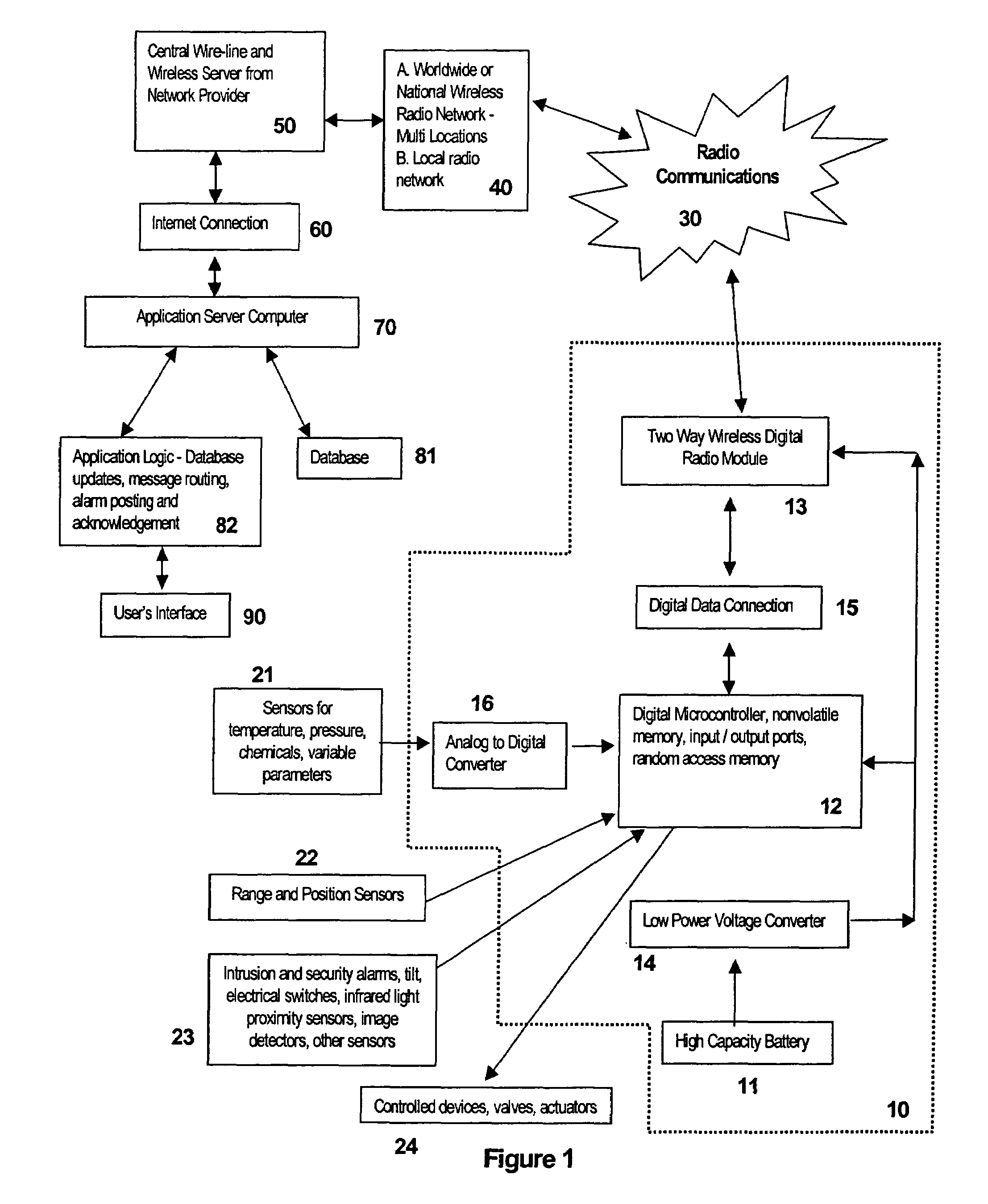
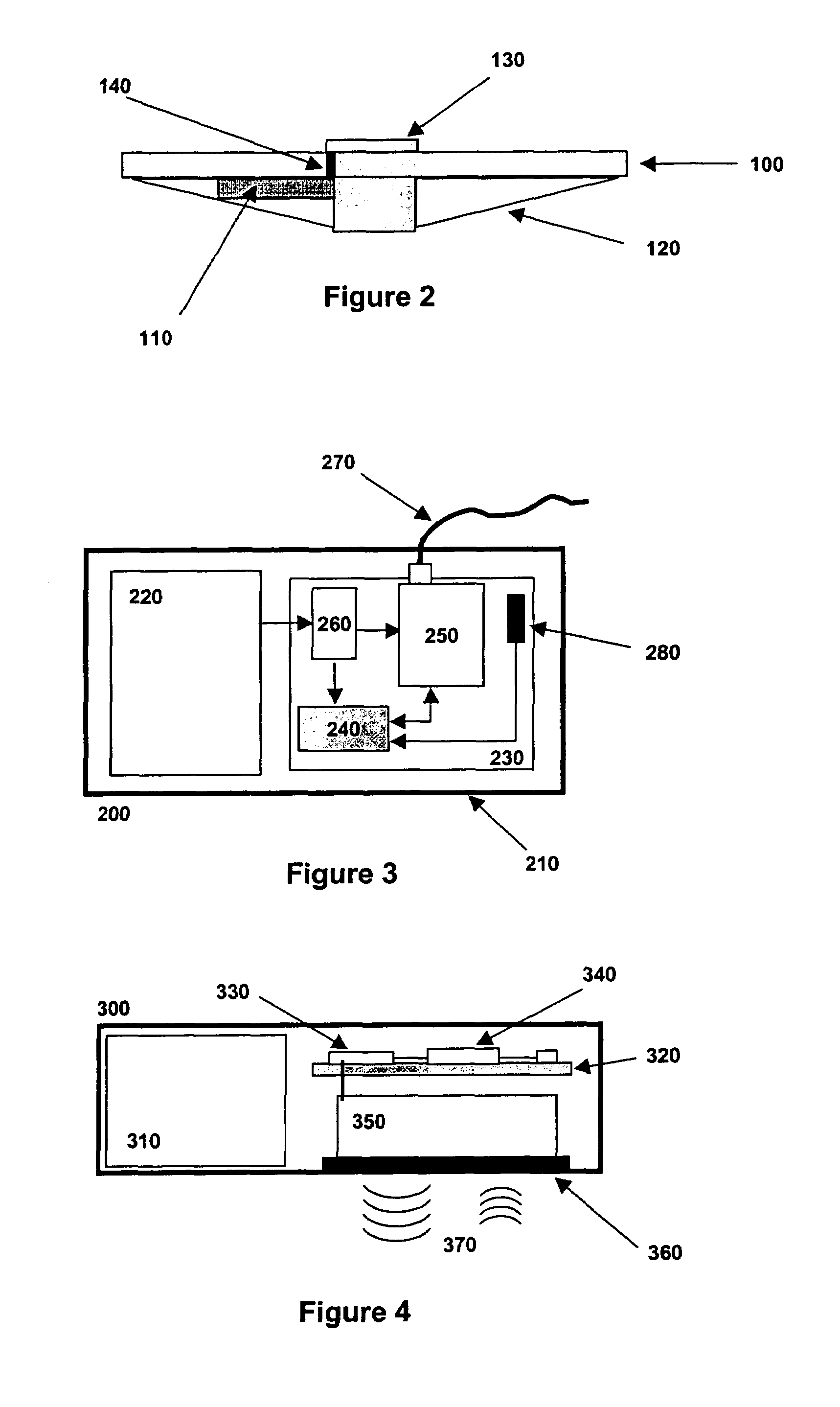
[0010]The present invention provides a system and method for combining self-contained power, electronics, communications, computational capability and sensors into a low cost and low power device integrated directly into and mounted on an enclosure barrier such as a manhole cover to provide sensing and rapid early warning of problems in the enclosure or around the enclosure barrier. Specifically, the invention includes a communications unit to provide communications from the device to a remote user of the system; a power source to provide constant and reliable power to the device; a microcontroller that can monitor sensor inputs and control communications and device operations; electronics that provide a means to provide appropriate power and current to the communications device, microcontroller, and sensors; and sensors which monitor parameters inside the enclosure or in the vicinity near the enclosure. The present invention also provides a low cost and low labor installation and maintenance process. Instead of expensive and time-consuming trenching at a site to provide power and communications, the invention provides a means for very low power consumption thereby enabling the use of small standard off-the-shelf battery packs to provide months of continuous operation, and wireless communications that eliminate the need for wires.
[0011]The system and method of the present invention also provides the following: (a) autonomously operations for months without need for external power, although external power may be used if it is available; (b) ease of integration and mounting into the enclosure barrier such as a manhole cover so that the operation of the enclosure barrier is not impeded and physical entry into the enclosure for installation is unnecessary; (c) rapid and reliable communications from the remote site to various real-time receivers that may include computers and electronic mail, personal digital assistants, phones, cell phones, and pagers; (d) generation of immediate alarms when thresholds of sensors have been exceeded or switches have been tripped; (e) monitoring of various conditions in and around the enclosure at short enough time intervals to provide sufficient time for communications and response in time for the prevention of an activity to be avoided, such as a sewage spill or illegal entry.
[0012]In the preferred embodiment, the present invention provides sanitation system operators a new way to routinely monitor and detect spills, anticipate overflows, detect illegal entry into the manholes, as well as monitor other environmental and process parameters of the sewage system such as flows, levels, gas content and sewage content. Furthermore, the invention detects spills rapidly to cause a response, thereby reducing damage to the environment, including potential pollution to receiving waters such as streams, lakes or the ocean. In addition, this invention can significantly reduce costs for sanitation system operators who have strict liability for spills occurring in their systems. Because the system is integrated directly into the manhole cover, there is no installation in the manhole shaft itself and no need to enter the manhole, further reducing risk and costs of installation.

Problems solved by technology

Sanitation and waste water systems are becoming increasingly expensive to operate and face daunting environmental, community and regulatory pressures.
Agencies and organizations that manage sanitation systems face complex and costly problems.
Three of the main problems facing sanitation system operators are sewage spills, treatment failure, and illegal dumping.
The first two of these problems often result in uncontrolled spills of septic materials into the environment, causing environmental damage, health risks, and high cleanup and mitigation costs, while the third problem respectively generates a potential danger to treatment systems, the environment and uncontrolled liability for the sanitation operators.
Sewage spills are becoming more common and more costly for agencies and organizations that are responsible for handling waste disposal and treatment.
Increased population is putting severe strain on sewage systems, systems are aging and becoming more susceptible to leaks and spills, and costs of spills which include clean-up, mitigation and fines by regulatory agencies are skyrocketing.
It is not uncommon for sanitation agencies to be fined millions of dollars for sewage spills, especially if they are large or reach receiving waters.
Sewage spills also create serious public relations problems for operating agencies, and it is not uncommon for sewage to back up into residences and commercial facilities, creating serious liabilities for the agencies and very costly and time consuming clean-up.
Sewage spills are caused by many problems, but three primary causes are often cited: grease buildup from illegal discharges by restaurants, other commercial businesses or residences that use fat, lard or grease in food or industrial processing; structural problems in sewage pipes caused by the intrusion of plant roots or pipe breakages that are often exacerbated by objects such as rags that are thrown into the sewer; and “infiltration and inflow”, overflows caused by leaks into the system that often occur during times of high rainfall or runoff.
Sewage spills often begin, then, with sewage pipes that are either blocked or are at capacity and overflowing due to high flows.
Currently there is no practical early warning system to provide system operators a cost-effective means to prevent a spill before it happens.
By the time sewage spills are noticed by the public, it is too late—the spill has already occurred, and it is just a question of how much sewage has spilled into the environment, whether the spill has reached clean receiving waters, how much it will cost and how long it will take to clean-up the problem and how large the fines will be.
A second major problem for sanitation agencies is a loss of treatment due to the killing off of beneficial treatment bacteria at the sewage treatment plant.
If incoming waste is toxic to the beneficial bacteria, a massive die-off can occur without warning, and sewage can be spilled or otherwise discharged that is unknowingly under-treated or untreated.
In addition, illegal dumping of materials into manholes is a common problem.
The source could be illegal operations of commercial establishments that face large costs associated with disposal of hazardous waste, including dumping of trucked sewage and septic pumping, or simple vandalism.
Covert dumping of illicit drug lab waste is an additional source of problems.
Rather than pay high fees at legal dumping stations, truckers of hazardous waste, include septic waste, could access a remote manhole illegally and dump large quantities of materials with low probability of detection and prosecution.
Such uncontrolled dumping into sewage systems is a major problem for the sanitation industry because the sewage system operators are ultimately responsible for what is dumped into their systems and the operators have little or no chance of catching or preventing illegal dumping.
Illegal access to manholes has forced some sanitation agencies to weld down their manholes, creating a significant deterrent to illegal access, but at the same time causing operational problems, including delayed or deferred maintenance or in the case of an emergency, significant delay in accessing a manhole through the manhole cover.
These methods suffer from one or more of the following problems: (a) installation requires entry into the manhole, thus high cost and higher safety risk from entering the manhole; (b) the system requires wired communications, thus trenching around the manhole; (c) the system requires continuous 120 Volt AC power, thus trenching around the manhole; (d) the total installation is costly, limiting the deployment of these systems to no more than a few select manholes.

Method used


Image

  • Remote sensing and communication system
  • Remote sensing and communication system
  • Remote sensing and communication system

Examples


Embodiment Construction

[0023]The present invention provides a system and method for combining self-contained power, electronics, communications, computational capability and sensors into a low cost and low power device integrated directly into and mounted on an enclosure barrier such as a manhole cover to provide sensing and rapid early warning of problems in the enclosure or around the enclosure barrier. The sensors include, but are not limited to, a level sensor, a flow sensor, a pressure sensor, a ranging sensor, an ultrasonic ranging detector protected by a water resistant fabric, a gas sensor, an odor sensor, a temperature sensor, an optical monitor, such as a video camera, still camera or an infrared sensor. Furthermore, the sensors can be physically disconnected from the manhole cover and mounted on the walls or the floor of the manhole. For example, a float switch may be remotely located at the bottom of the manhole with an infrared or ultrasonic means of contacting the housing. In the case of a t...


PUM


Abstract

A remote sensing system and method for instrumenting the entries to manhole enclosures, in order to provide a platform and means for sensing environmental parameters within and around the enclosures and wirelessly transmitting those parameters to a distant site. The system comprises a housing with sensor for monitoring environmental parameter in the vicinity of the manhole. A microcontroller in the housing sends the parameters to a radio module, which transmits the parameters to a communication device for alerting a user that a manhole has been tampered with.

Description

FIELD OF THE INVENTION[0001]This invention relates generally to a system and method for instrumenting the entries to enclosures, in order to provide a platform and means for sensing environmental or process parameters within and around the enclosures and wirelessly transmitting those parameters to a distant site.BACKGROUND OF THE INVENTION[0002]Sanitation and waste water systems are becoming increasingly expensive to operate and face daunting environmental, community and regulatory pressures. Agencies and organizations that manage sanitation systems face complex and costly problems. Three of the main problems facing sanitation system operators are sewage spills, treatment failure, and illegal dumping. The first two of these problems often result in uncontrolled spills of septic materials into the environment, causing environmental damage, health risks, and high cleanup and mitigation costs, while the third problem respectively generates a potential danger to treatment systems, the e...

Claims


Application Information

Patent Timeline
Patent Type & Authority Patents(United States)
IPC IPC(8): G08B1/08H04Q7/00
CPCG08B13/149G01F15/063G08C17/00G08C17/02H04W88/18G08B1/08
Inventor DRAKE, DAVID A.QUIST, GREGORY M.
Owner HADRONEX LLC
Learn More