
Self-test digital phase-locked loop and method thereof

a phase-locked loop and self-test technology, applied in the field of phase-locked loops and methods thereof, can solve the problems of high manufacturing cost and time-consuming, and achieve the effect of easy and non-tidy circuit debugging

Inactive Publication Date: 2007-11-06
ETRON TECH INC
View PDF2 Cites 6 Cited by
  • Summary
  • Abstract
  • Description
  • Claims
  • Application Information

AI Technical Summary

Benefits of technology

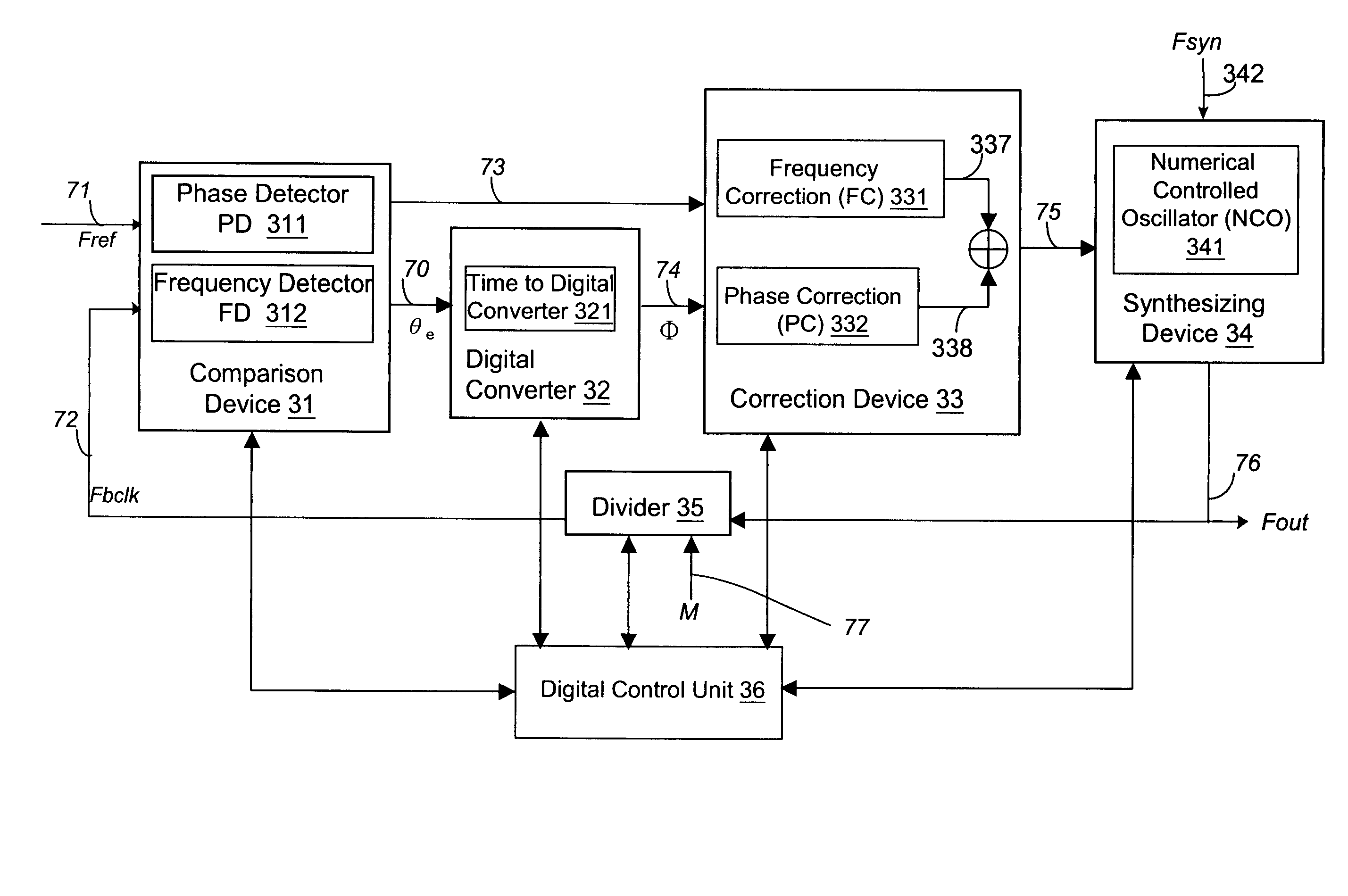
The patent describes a self-test digital phase-locked loop (PLL) that can test its operation without needing large testing circuits embedded in the PLL. The method uses a locking mechanism to produce information about phase adjustment and frequency adjustment. The PLL circuit internally generates a set of digital parameters and a data capture circuit selectively captures these parameters based on certain criteria. The self-test PLL offers cost advantages over conventional testing methods, provides flexibility for adjusting the frequency and phase associated with three modes, and makes debugging circuits easier and non-tedious. The self-test PLL also has control circuitry in digital form suitable for implementation in an ASIC chip.

Problems solved by technology

For measuring these characteristics, a complicated testing machine is required that causes the high manufacturing cost and time consuming.

Method used


Image

  • Self-test digital phase-locked loop and method thereof
  • Self-test digital phase-locked loop and method thereof
  • Self-test digital phase-locked loop and method thereof

Examples


Embodiment Construction

[0021]FIG. 2 is a schematically block diagram of a digital phase-locked loop (PLL) in accordance with one embodiment of the present invention. The digital phase-locked loop (PLL) 20 includes a self-test digital PLL circuit 21 and a register 23 used by a data capture circuit 22. In one embodiment, the self-test digital PLL circuit 21 receives an input signal 211(Fref) and multiplies its frequency by 214(M), for example, an integer, then outputs the output signal 212(Fout) and generates a set of digital parameters 213. In the embodiment, the digital parameters 213, not limited to, may be initial values, frequency gain, phase gain, flags, jitter, frequency, control signals, etc. The register 23 is configured for receiving and storing the digital parameters 213. The data capture circuit 22 is configured for coordinating the self-test digital PLL circuit 21 and the register 23 to selectively capturing the set of digital parameters 213 based on a set of criteria. Using the digital paramet...


PUM


Abstract

A phase-locked loop (PLL) apparatus utilizes a digital control unit to perform a stable phase-locking and self-testing. The PLL circuit internally generates a set of digital parameters. The set of digital parameters are configured to be as the basis of testing. Therefore, the PLL can be tested by a digital way instead of an analog way. In addition, a method of locking a PLL includes three operating modes, and the data capture circuit captures some data generated by phase-locked loop (PLL) during these operation.

Description

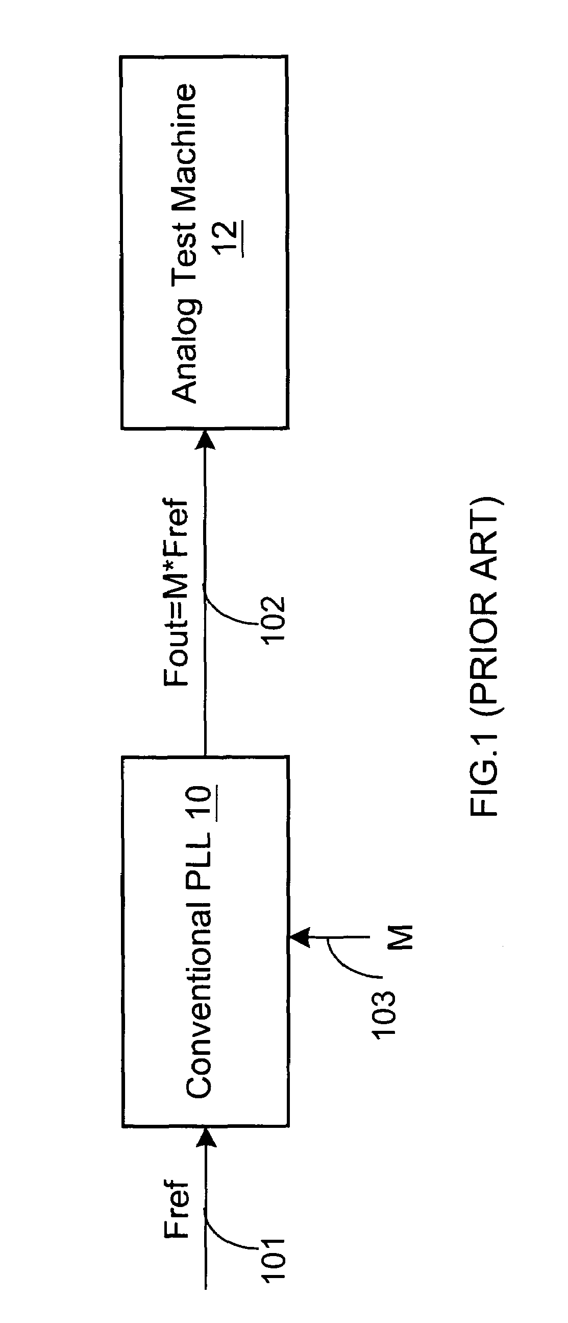
BACKGROUND OF THE INVENTION[0001]1. Field of the Invention[0002]The present invention relates to a phase-locked loop (PLL), and more especially, to a self-test PLL and method thereof.[0003]2. Background of the Related Art[0004]With the development of technology, circuit design has been evolved from single chip to SOC chip. For IC of mixing signals or SOC, phase-locked loop (PLL) is essential and applied to LCD controller, video decoder, etc. It is necessary for testing to consider the difference between analog circuit and digital circuit. However, the conventional testing of PLL is executed in the way of analog test machine.[0005]The phase-locked loop (PLL) block is a feedback control system that automatically adjusts the phase and frequency of a locally generated signal to match the phase and frequency of an input signal. FIG. 1 is a block diagram of a conventional phase-locked loop (PLL). A conventional PLL 10 receives the input signal 101(Fref) and multiplies its frequency by 103...

Claims


Application Information

Patent Timeline
Patent Type & Authority Patents(United States)
IPC IPC(8): H03L7/085
CPCG01R31/31725G01R31/31727H03L7/08G01R31/3187H03L7/0991
Inventor LEE, MING-FUO
Owner ETRON TECH INC
Learn More