
Method for accurately setting parameters inside integrated circuits using inaccurate external components

Active Publication Date: 2007-11-06
INTERSIL INC
View PDF11 Cites 17 Cited by
  • Summary
  • Abstract
  • Description
  • Claims
  • Application Information

AI Technical Summary

Benefits of technology

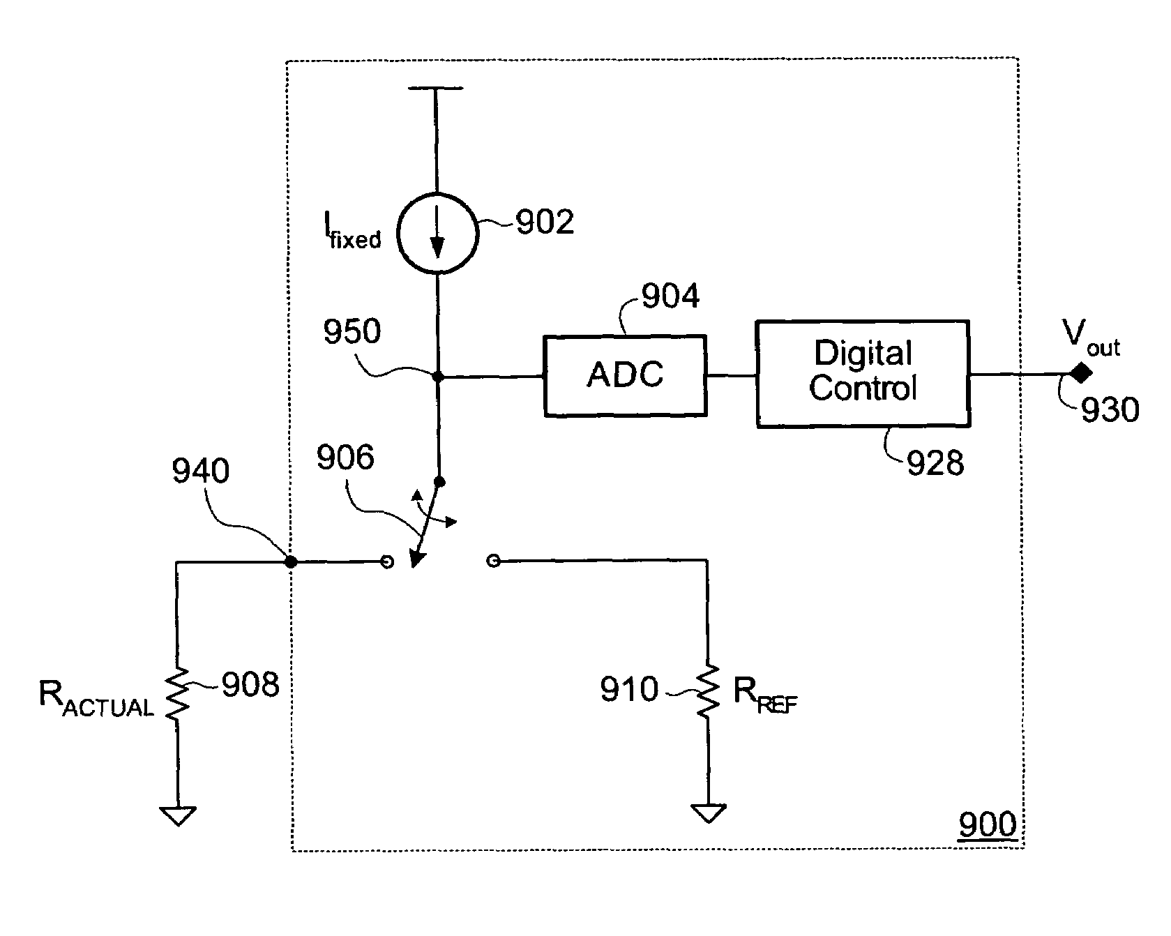
[0041]In one set of embodiments, a nominal resistor value for generating a specific output voltage may be selected from a set of user specified nominal resistor values. The nominal resistor values may correspond to values of commercially available resistors that may physically be included in a voltage converter circuit. In one embodiment, an integrated circuit (IC) may be configured to accurately control the output voltage using a single external resistor. The IC may be configured to measure the actual value of the external resistor, and, from the actual value of the external resistor, determine which of the specified nominal resistor values was intended to be used in generating the output voltage. The intended, or “ideal” (i.e. nominal) resistor value—rather than the actual value of the external resistor—may then be used to control the output voltage. The set of specified nominal resistor values may be chosen such that the total measurement error incurred during measurement of the actual value of the external resistance is less than the spacing between adjacent ones of the specific resistor values. The circuit or IC may therefore reliably identify the nominal resistor value corresponding to the external resistor, allowing for more precise control of the output voltage by using the identified nominal resistor value.
[0045]Specifying a first external resistor as a ‘coarse’ value, and using an additional pin to couple an additional external resistor as a ‘fine’ value may lead to a higher number of potential values for the nominal resistance. The coarse and fine resistors may have similar tolerances. By using methods similar to those described above, a coarse nominal value by way of the coarse resistor may be provided for the controlled parameter. The ratio of the coarse external resistor to the fine external resistor may then be used to ‘fine-tune’the controlled value relative to the coarse value. This may allow the external resistor errors to be substantially attenuated.

Problems solved by technology

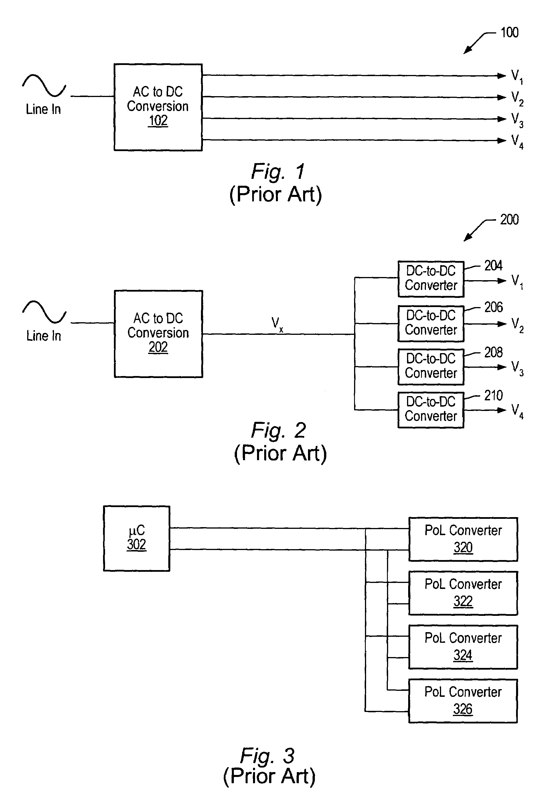
This rapid evolution has created new and significant problems in delivery of the power to and removal of waste heat from these ICs.
Power supply design is now a much more critical and difficult task than it was a few years ago.
However, it may not be practical to route high-current signals throughout a system.
In many power distribution systems it is typically not enough to just distribute power around a system to the various POLs.
Dense electronic systems often generate excessive waste heat.
Routing of such signals is often difficult, while no true communication is established between various POL converters and / or between the POL converters and any other elements of the system.
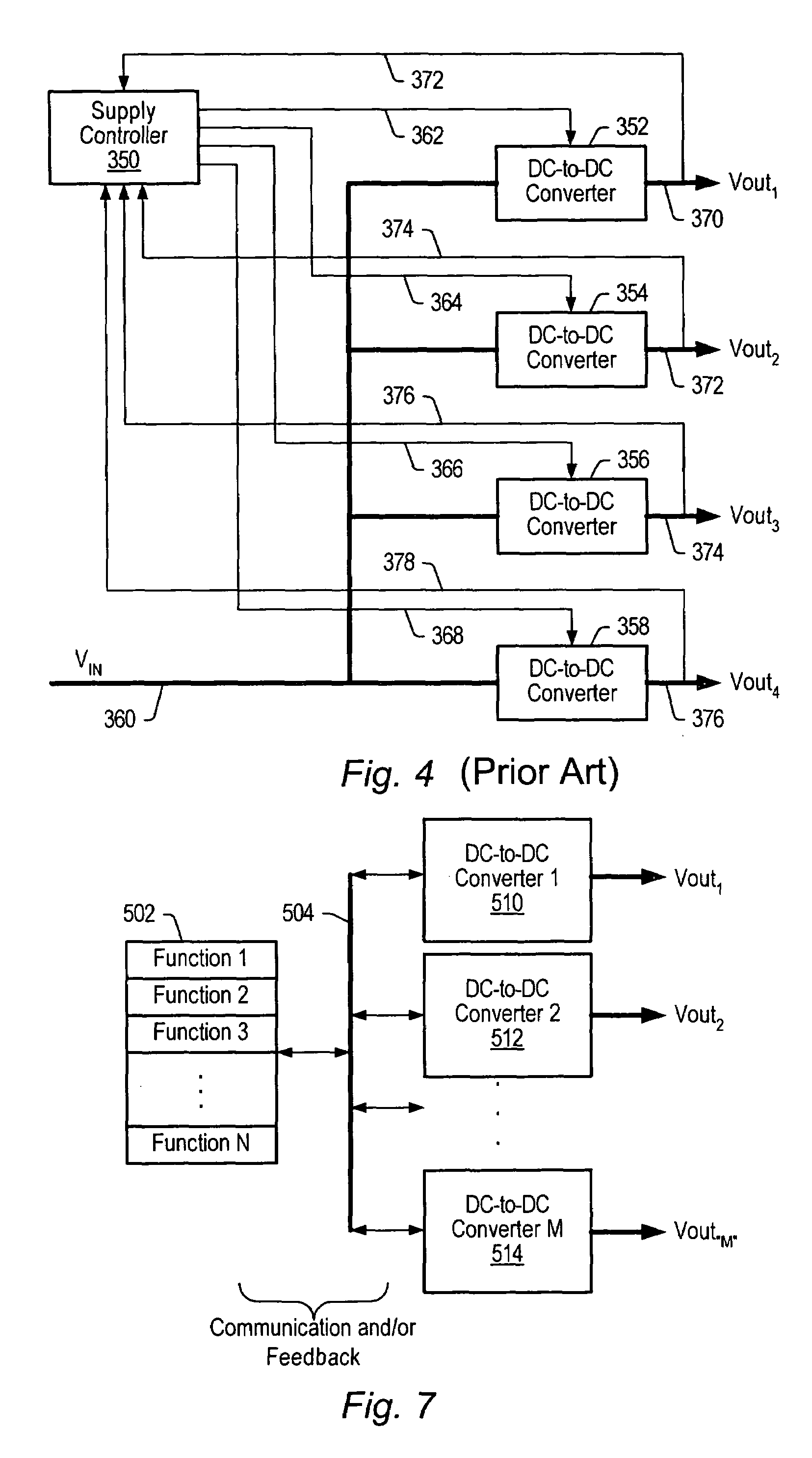
In general, microcontroller 302 checks status for one POL converter at a time, which may be viewed as a disadvantage when more interactive, real-time communication is desired in a system.
Increasing pin count may become expensive due to the increase in die area and package size.
Also, with increasing number of output voltage settings, digital control generally becomes impractical without the use of a complicated digital bus structure. FIG. 6 shows a typical analog method to control the output voltage at node 660.
This often results in the need to use more expensive high-precision resistors.

Method used


Image

  • Method for accurately setting parameters inside integrated circuits using inaccurate external components
  • Method for accurately setting parameters inside integrated circuits using inaccurate external components
  • Method for accurately setting parameters inside integrated circuits using inaccurate external components

Examples


Embodiment Construction

[0059]The following references are hereby incorporated by reference in their entirety as though fully and completely set forth herein:

[0060]U.S. Patent Application Publication No. 2004 / 0201279 (Ser. No. 10 / 820,976), titled “Method And Apparatus For Improved DC Power Delivery, Management And Configuration,” filed Jun. 21, 2004.

[0061]U.S. patent application Ser. No. 11 / 198,698, titled “Method For Using a Multi-Master Multi-Slave Bus For Power Management,” filed Aug. 5, 2005.

[0062]FIG. 7 is a block diagram of one embodiment of a power distribution system. As shown, the common functions required in a complex DC power system may be combined in a single controller rather than treated as separate IC functions. As illustrated in the embodiment of FIG. 7, a controller 502 managing functions 1 through N may be coupled to DC-to-DC converters 1 through M (illustrated by example as power converters 510, 512 and 514) via a digital bus 504. Digital bus 504 may be a serial bus enabling communicatio...


PUM


Abstract

The control precision of one or more parameters of an integrated circuit (IC), for example the output voltage of a voltage regulator comprised in the IC, may be improved even when using inaccurate components external to the IC. Control of the output voltage, or any parameter, using components external to the IC may include coupling a resistor to the IC and measuring the actual resistance value of the resistor, and based on the measured value, selecting a nominal resistance value from a set of resistance values previously specified by the user. The output voltage, or parameter, may be generated according to the nominal resistance value instead of the actual resistance value, thereby reducing the error that may be incurred due the actual resistance value of the resistor not matching the expected nominal value of the resistor. The difference between each adjacent resistance value in the set of resistance values may be selected to be greater than the greatest measurement error that may be incurred during measuring the actual resistance value.

Description

[0001]This application claims benefit of priority of U.S. provisional application Ser. No. 60 / 723,282 titled “System and Method for Implementing Distributed Power Management”, filed Oct. 3, 2005.BACKGROUND OF THE INVENTION[0002]1. Field of the Invention[0003]This invention relates to power converters and, more particularly, to incorporating power-management functions in power converters.[0004]2. Description of the Related Art[0005]From 1995 to 2001, the highest density processors from manufacturers such as Intel went from a power consumption rate of about 30 Watts at 3.3 V to a power consumption rate of about 90 Watts delivered at 1.5 V. A simple application of the power-voltage-current relationship reveals that the total current consumed by these chips has increased from nine amps to about 60 amps in a very short time period. There are similar analogies with all larger digital integrated circuits (ICs).[0006]This rapid evolution has created new and significant problems in delivery ...

Claims


Application Information

Patent Timeline
IPC IPC(8): G05B24/02
CPCH02M3/157H02M2001/008H02M2001/0025H02M1/0025H02M1/008
Inventor FERNALD, KENNETH W.
Owner INTERSIL INC
Learn More