
Electric vehicle motion sensor

a technology for motion sensors and electric vehicles, applied in the direction of electrical apparatus casings/cabinets/drawers, coupling device connections, instruments, etc., can solve the problems the main circuit board of vibration and noise, and the inadvertent deployment of safety systems or vehicle reaction systems

Active Publication Date: 2007-11-06
VEONEER US LLC
View PDF6 Cites 63 Cited by
  • Summary
  • Abstract
  • Description
  • Claims
  • Application Information

AI Technical Summary

Benefits of technology

[0012]Damping compound may be used in the sensor assembly to dampen the response of the daughter board assembly. The damping compound may be disposed between the daughter board assembly and the housing element.

Problems solved by technology

Since inadvertent deployment of safety systems or vehicle reaction systems is highly undesirable, the control unit needs to reliably detect these events.
One source of vibration and noise is the main circuit board itself, since the sensing assemblies are typically mechanically coupled to the main circuit board, which has electrical cabling attached.

Method used


Image

  • Electric vehicle motion sensor
  • Electric vehicle motion sensor
  • Electric vehicle motion sensor

Examples


second embodiment

[0032]Another variation of the sensor assembly 110 is shown as a second embodiment in FIGS. 4-5. In this variation, the daughter board assemblies 112 and circuit board 124 are mounted to the housing lid 130. The receiving feature on the housing lid 130 is an upstanding wall 134. The housing lid 130 on which the upstanding wall 134 is located is the lid of the sensor assembly 110. Similar to the variation shown in FIGS. 1-3, in this variation, the daughter board assemblies 112 are positioned spaced from the circuit board 124. Clips 138 act as a retention feature to hold the daughter board assemblies 112 to the upstanding walls 134. After the daughter board assemblies 112 and the circuit board 124 are secured to the housing lid 130, the housing body 142 of the sensor assembly 110 (shown in FIG. 4) is secured to the housing lid 130.

[0033]In the variation of FIGS. 4-5, damping compound, such as elastomeric foam (not shown), may be used in the sensor assembly 110 to dampen the response o...

third embodiment

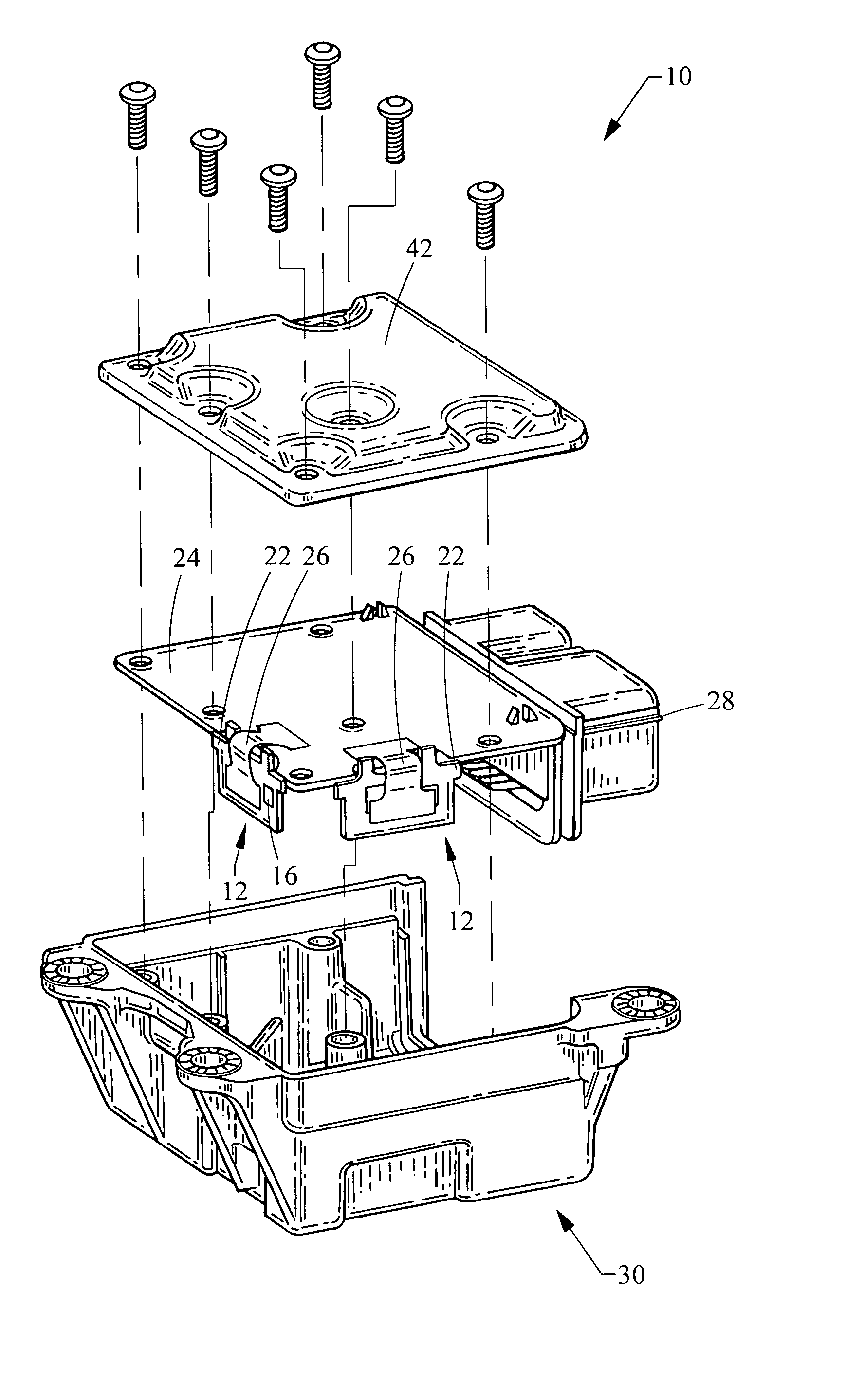
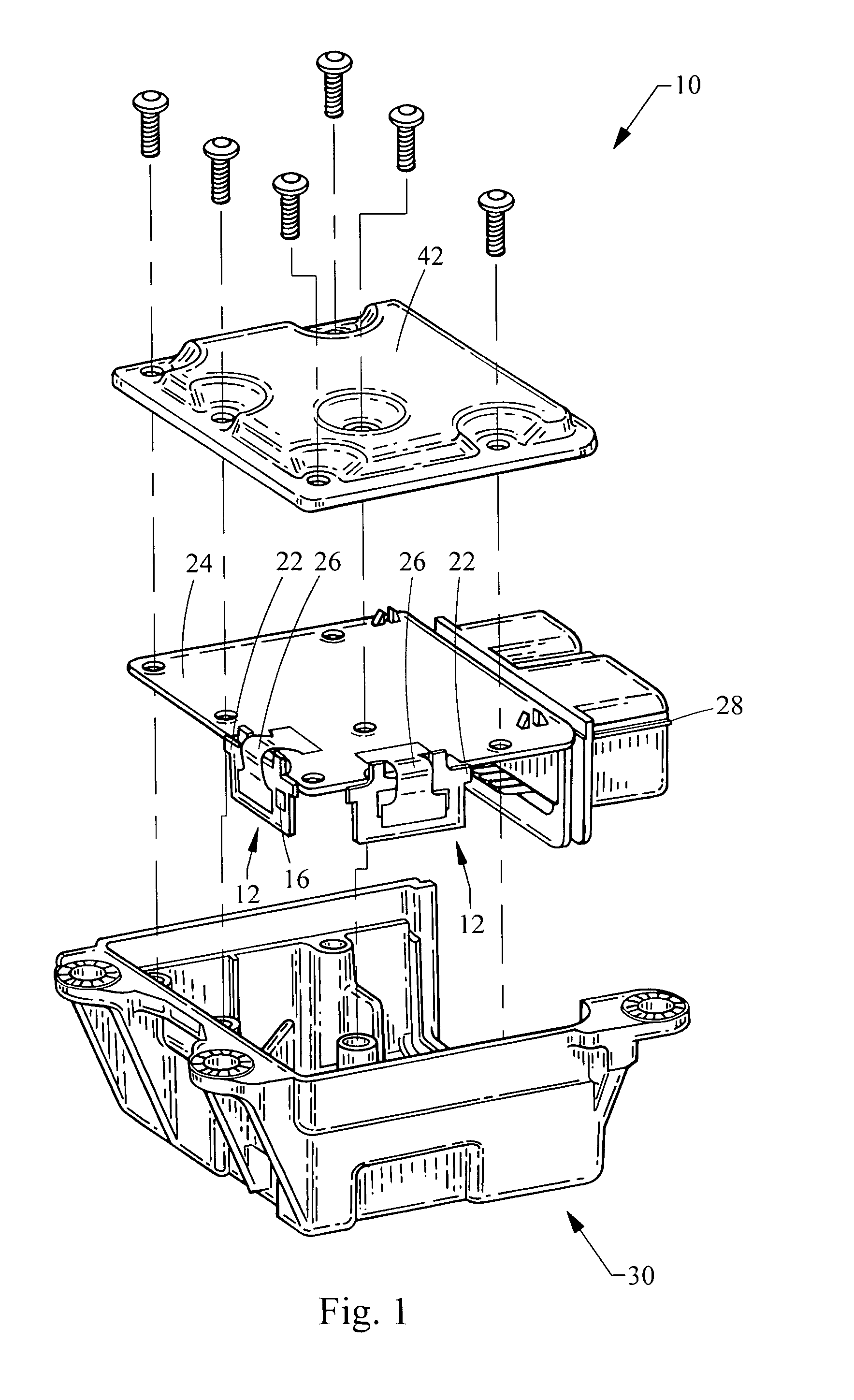
[0034]Referring to FIGS. 6-7, a motor vehicle sensor assembly 210 is shown. A circuit board 223 having electronic components (not shown) has a flexible portion 226 separating a first rigid portion 224 comprising a main circuit board 225 from a second rigid portion 212 comprising a daughter board assembly 214. The daughter board assembly 214 includes sensors (not shown) similar to the features of the daughter board assemblies 12 of FIGS. 1-2, such as an accelerometer 16 and an angular rate sensor (ARS) 18, 20.

[0035]In the sensor assembly 210 of FIGS. 6-7, the housing 230 includes receiving features 232, in the form of sleeves, slots, or pockets, that are adapted to receive and engage alignment features 222 of the second rigid portion 212 of the circuit board 223. FIG. 7 shows the first rigid portion 224 of the circuit board 223 mounted to the bottom of the housing 230, while the second rigid portion 212 of the circuit board 223 is mounted by engaging the alignment features 222 of the...


PUM


Abstract

A motor vehicle motion sensor assembly includes a daughter board assembly having an alignment feature, a circuit board having electronic components, and a housing element having a receiving feature for receiving the daughter board assembly. The circuit board is electrically connected with the daughter board assembly by a flexible electrical connector. The circuit board is further connected with an external circuit connector. The alignment feature of the daughter board assembly is adapted to engage the receiving feature of the housing element.

Description

BACKGROUND[0001]1. Field of the Invention[0002]This invention generally relates to motor vehicle sensor system assemblies. More specifically, the invention relates to motor vehicle sensor system assemblies having sensors to determine the occurrence of a change in vehicle attitude or motion.[0003]2. Description of Related Art[0004]In motor vehicle design, vehicle safety systems are becoming increasingly important. To that end, vehicles often include sensor systems used to alert the driver, and in some cases, to automatically deploy certain safety and dynamic stability systems. Sensor systems may be configured to trigger vehicle safety systems or vehicle reaction systems, such as deployment of airbags, automatic braking, or reduction of engine torque upon the occurrence of predetermined conditions. For example, electronic stability control (ESC) systems automatically control vehicle functions to control loss of directional stability or intervene where vehicle rollover conditions are p...

Claims


Application Information

Patent Timeline
IPC IPC(8): H01R12/00
CPCB60R21/01G01D11/245G01P1/023G01P15/18H01R13/512H01R13/6658H01R23/70H05K1/141H01R12/79H05K5/0078H01R12/721Y10S439/913H01R2201/20H01R2201/26H05K1/148H05K2203/167B60R2021/01006
Inventor STILL, CHARLESGRAAN, HANS
Owner VEONEER US LLC
Learn More