Method of manufacturing ink jet recording head, ink jet recording head, and ink jet cartridge
a technology of ink jet recording head and manufacturing method, which is applied in printing and other directions, can solve the problems of affecting the yield affecting the precision of manufactured head, and affecting the quality of high-precision head manufacturing, so as to prevent physical breakage of filter structure, facilitate manufacturing, and improve the effect of strength
- Summary
- Abstract
- Description
- Claims
- Application Information
AI Technical Summary
Benefits of technology
Problems solved by technology
Method used
Image
Examples
first example
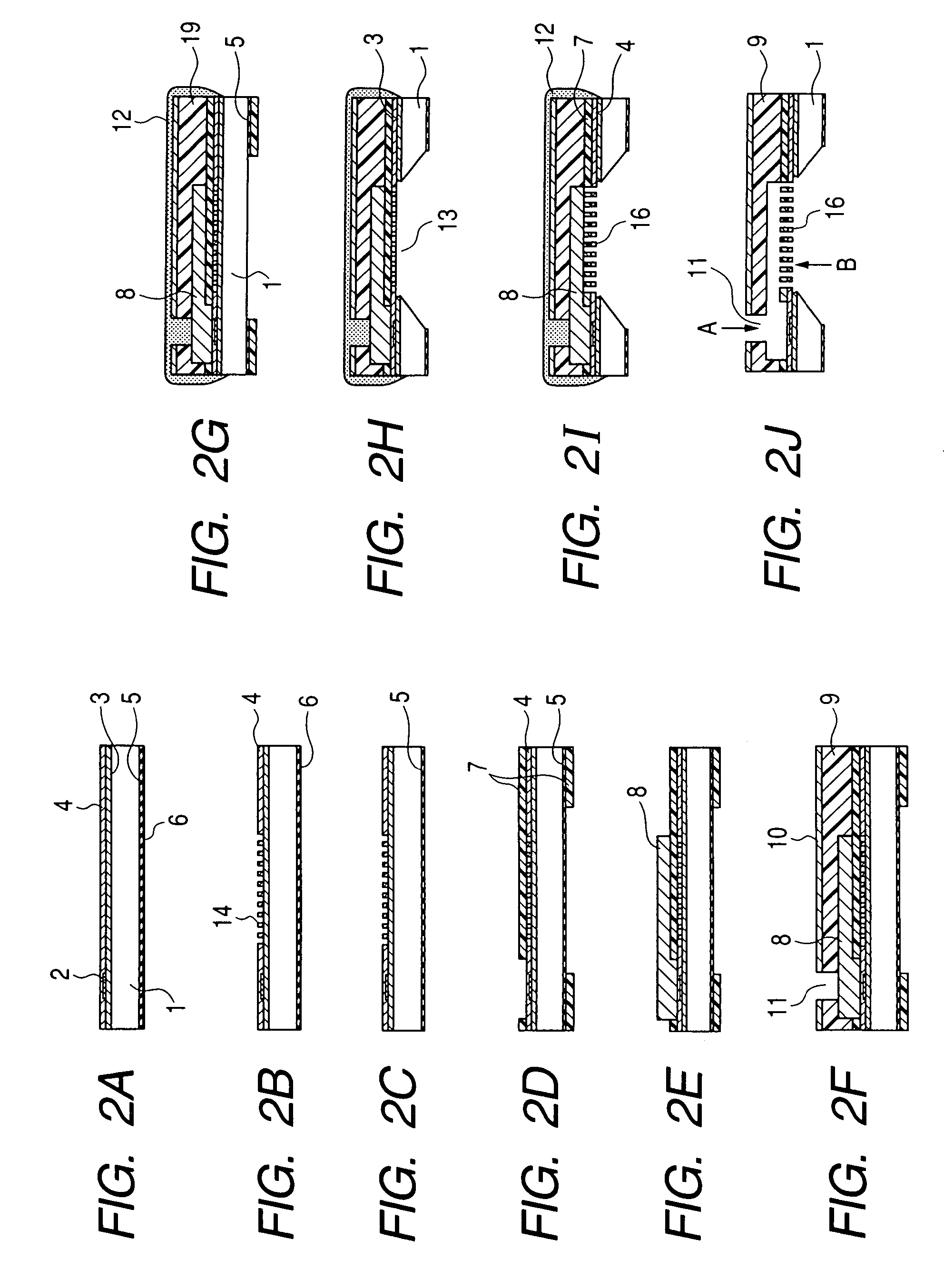
[0034]Next, steps of manufacturing an ink jet recording head according to a first example of the present invention will be described with reference to FIGS. 2A to 2J. FIGS. 2A to 2J are schematic sectional views showing the steps of manufacturing the ink jet recording head according to the first example of the present invention. It is to be noted that FIGS. 2A to 2J show sections in A-A line of FIG. 1B.
[0035]An Si substrate 1 shown in FIG. 2A has a crystal orientation of a plane. In the present example, the Si substrate 1 having the crystal orientation of the plane will be described as an example, but the plane orientation of the Si substrate 1 is not limited to this orientation.
[0036]An SiO2 film 3 which was an insulating layer was formed on the surface (first surface) of the Si substrate 1, a plurality of ink discharge pressure generation elements 2 constituted of heat generating resistors and the like were constituted on the film, and further an electric signal circuit (not sho...
second example
[0051]Next, steps of manufacturing an ink jet recording head according to a second example of the present invention will be described with reference to FIGS. 5A to 5J. FIGS. 5A to 5J are schematic sectional views showing the steps of manufacturing the ink jet recording head according to the second example of the present invention, and FIGS. 5A to 5J show sections in A-A line of FIG. 1B.
[0052]An Si substrate 21 shown in FIG. 5A has a crystal orientation of a plane. Even in the present example, the Si substrate 21 having the crystal orientation of the plane will be described as an example, but the plane orientation of the Si substrate 21 is not limited to this orientation.
[0053]An etching-proof mask 25 and a polysilicon film 26 constituted of insulating films such as SiO2 and SiN films were formed over the whole back surface (second surface) of the Si substrate 21, and an SiO2 film 23 was formed into a film thickness of 1.1 μm as an insulating layer on the surface (first surface) of...
third example
[0067]FIG. 6 is a sectional view showing an ink jet recording head according to a third example of the present invention.
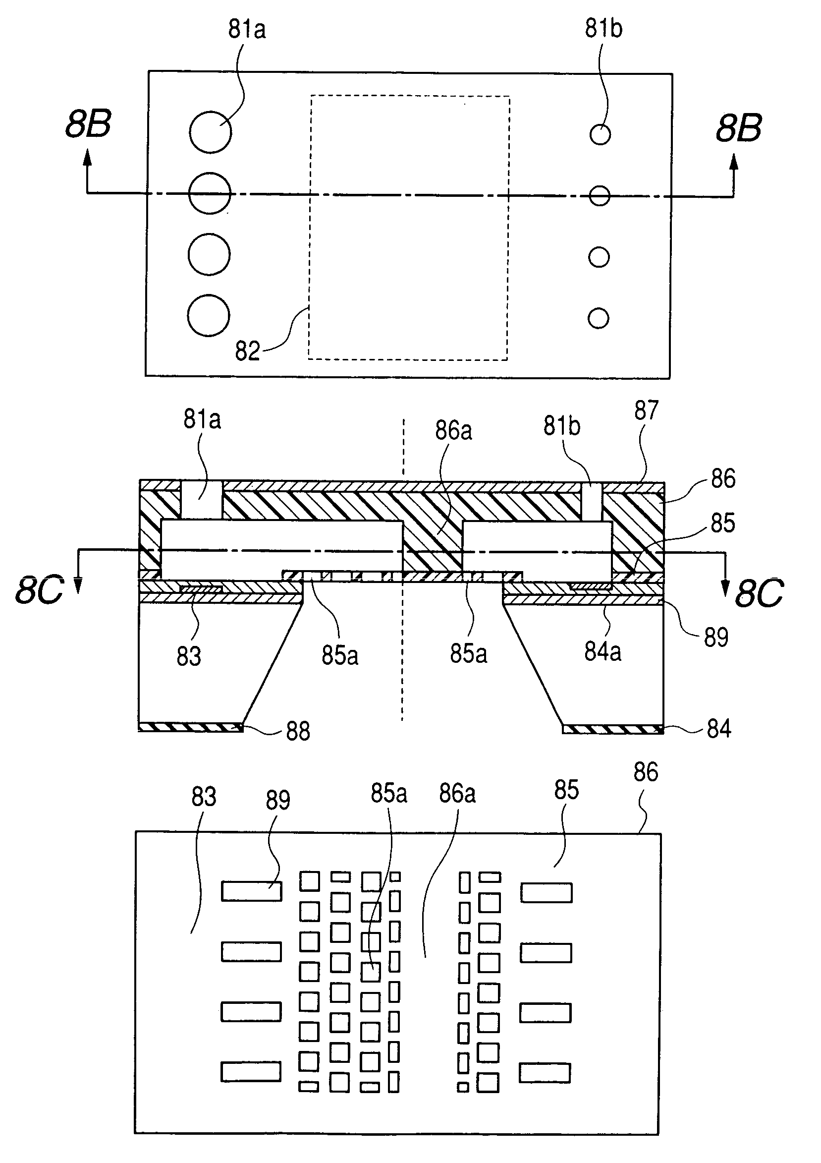
[0068]In the ink jet recording head of the present example, in a coating resin layer (nozzle forming member) 49 and a close contact enhancing layer 47 disposed on a first surface (upper surface) of an Si substrate 41, a portion existing in a middle area of an ink supply port 53 constitutes a support portion 60 which supports a membrane filter structure 56. The support portion 60 can be easily constituted by appropriately changing a shape of the pattern layer in the steps of manufacturing the ink jet recording head described in the first and second examples. Accordingly, for example, when ink flows into a nozzle channel from the ink supply port 53 with great force, the membrane filter structure 56 can be prevented from being pushed and broken by the ink. Therefore, strength of the membrane filter structure 56 against physical breakage can be enhanced.
[0069]It is to...
PUM
 Abstract
Description
Claims
Application Information
 - R&D
- Intellectual Property
- Life Sciences
- Materials
- Tech Scout
- Unparalleled Data Quality
- Higher Quality Content
- 60% Fewer Hallucinations
Browse by: Latest US Patents, China's latest patents, Technical Efficacy Thesaurus, Application Domain, Technology Topic, Popular Technical Reports.
© 2025 PatSnap. All rights reserved.Legal|Privacy policy|Modern Slavery Act Transparency Statement|Sitemap|About US| Contact US: help@patsnap.com


