Polling communication system and polling control method

a communication system and communication system technology, applied in the field of polling communication system and polling control method, can solve problems such as transmission collision, transmission/receiving using protocols, and transmission collisions that occur frequently

Inactive Publication Date: 2007-10-23
FUJITSU LTD
View PDF12 Cites 9 Cited by
  • Summary
  • Abstract
  • Description
  • Claims
  • Application Information

AI Technical Summary

Benefits of technology

[0017]It is a general object of the present invention to provide an improved and useful polling co

Problems solved by technology

In this case, when a plurality of sub stations simultaneously transmit data, transmission collision occurs.
Accordingly, there is a problem in that, in a high-traffic state, transmission collision occurs frequently and thr

Method used


Image

  • Polling communication system and polling control method
  • Polling communication system and polling control method
  • Polling communication system and polling control method

Examples


Embodiment Construction

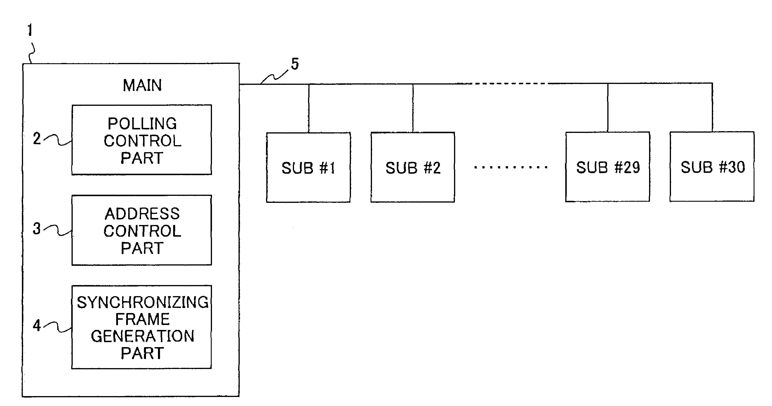
[0045]FIG. 4 is a block diagram for explaining an embodiment of the present invention. FIG. 4 illustrates a polling communication system in which a plurality of sub stations #1 through #30 are connected to a main station 1 through a bus 5. The main station 1 includes a polling control part 2, an address control part 3, and a synchronizing frame generation part 4. FIG. 4 shows a case where 30 sub stations are connected, however, the number of the sub stations can be selected arbitrarily. Further, the bus 5 can be a normal transmission channel that transmits data, or a distribution line and inside electric line or the like in the power-line carrier system.

[0046]The main station 1 does not perform polling uniformly to all the sub stations #1 through #30. The main station 1 performs the polling depending on states of the sub stations by dividing a predetermined polling cycle into a plurality of polling intervals, such as a polling interval in which a large number of pollings is made, a ...


PUM


Abstract

A polling communication system includes a main station and a plurality of sub stations connected to the main station. The main station includes an address control part and a polling control part. The address control part divides a predetermined polling cycle into a plurality of kinds of polling intervals each having a different number of times of polling, and holds addresses of polling target sub stations corresponding to the respective polling intervals. The polling control part switches the polling intervals and changes the addresses in the address control part according to states of the sub stations. Each of the sub stations includes another polling control part that sends a response when the sub station is polled by the main station.

Description

BACKGROUND OF THE INVENTION[0001]1. Field of the Invention[0002]The present invention relates to a polling communication system and a polling control method which communicate by successively calling a plurality of sub stations from a main station.[0003]2. Description of the Related Art[0004]FIG. 1A illustrates an example of a general structure of a system in which a plurality of sub stations are connected to a main station via a bus. In FIG. 1A, the system includes a host 100, a main station 101, sub stations 102, data terminal equipments (DTEs) 103, and a bus 104. M, M#1, M#2, . . . represent modems. #1, #2, . . . represent addresses of the sub stations 102. That is, data communication is performed between the data terminal equipments 103 and host 100 by connecting the plurality of sub stations 102 to the main station 101 that is connected to the host 100 through the bus 104.[0005]In such a system using a bus, communication method such as the CSMA / CD (Carrier Sense Multiple Access / ...

Claims


Application Information

Patent Timeline
IPC IPC(8): H04B1/44G06F3/00H04J3/16H04L12/403H04L12/43H04B3/54H04L12/28
CPCH04B3/542H04L12/403H04B2203/5408H04B2203/5445H04B2203/5425
Inventor KAKU, TAKASHIHIRAO, KYOKO
Owner FUJITSU LTD
Why Eureka
Try Eureka