
Manufacturing conduits for use in placing a target vessel in fluid communication with a source of blood

a technology for a target vessel and a fluid communication, which is applied in the direction of manufacturing tools, buttons, food shaping, etc., can solve the problems that heart disease remains the leading cause of death, and achieve the effect of sufficient rigidity and sufficient resilien

Inactive Publication Date: 2007-10-23
MEDTRONIC INC
View PDF59 Cites 8 Cited by
  • Summary
  • Abstract
  • Description
  • Claims
  • Application Information

AI Technical Summary

Benefits of technology

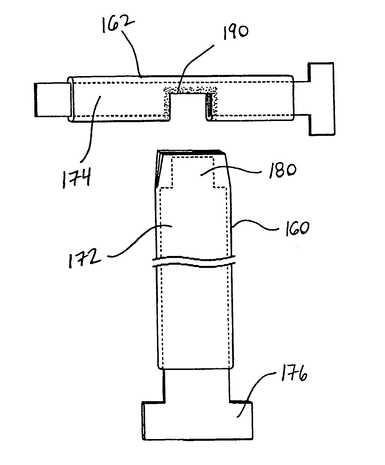
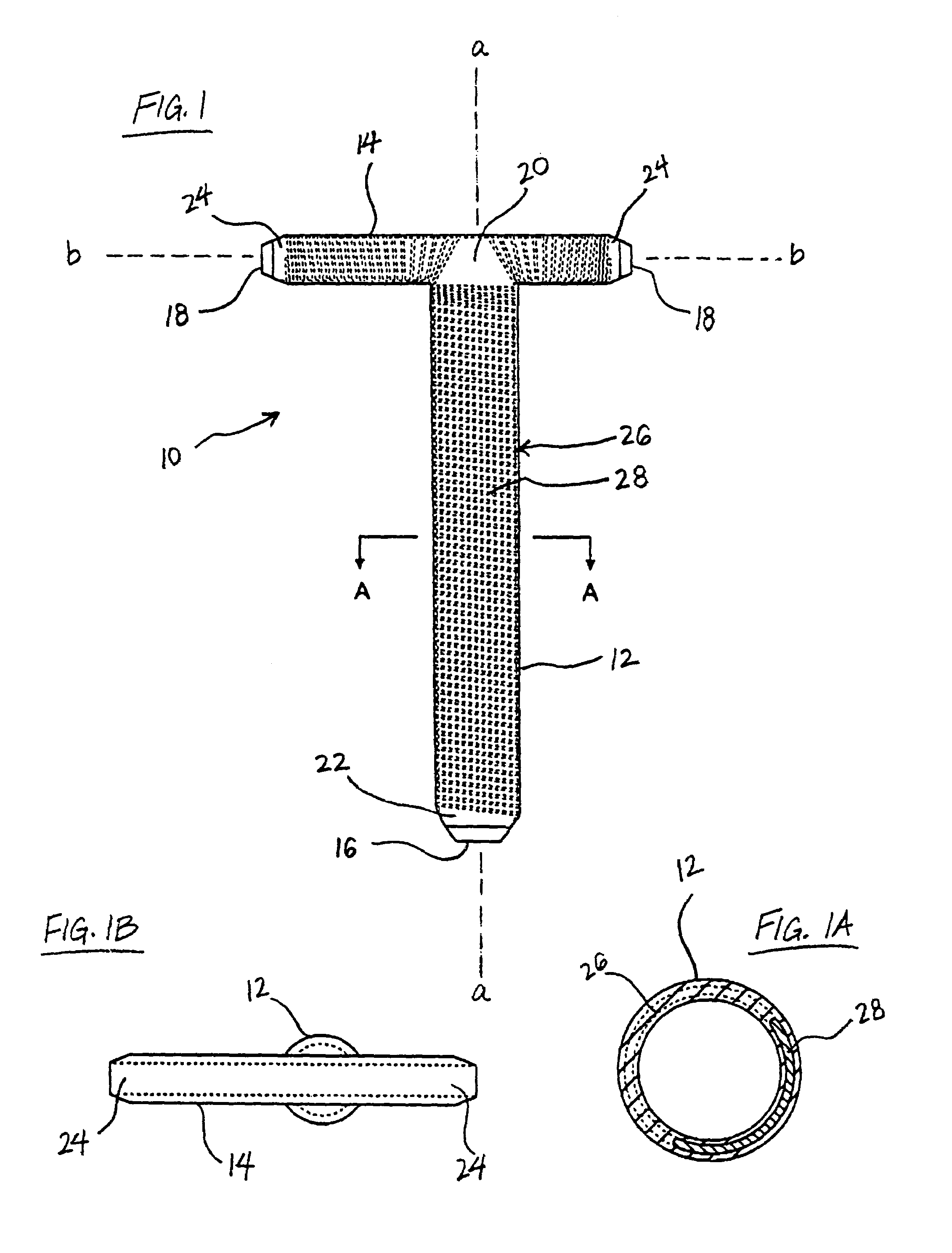
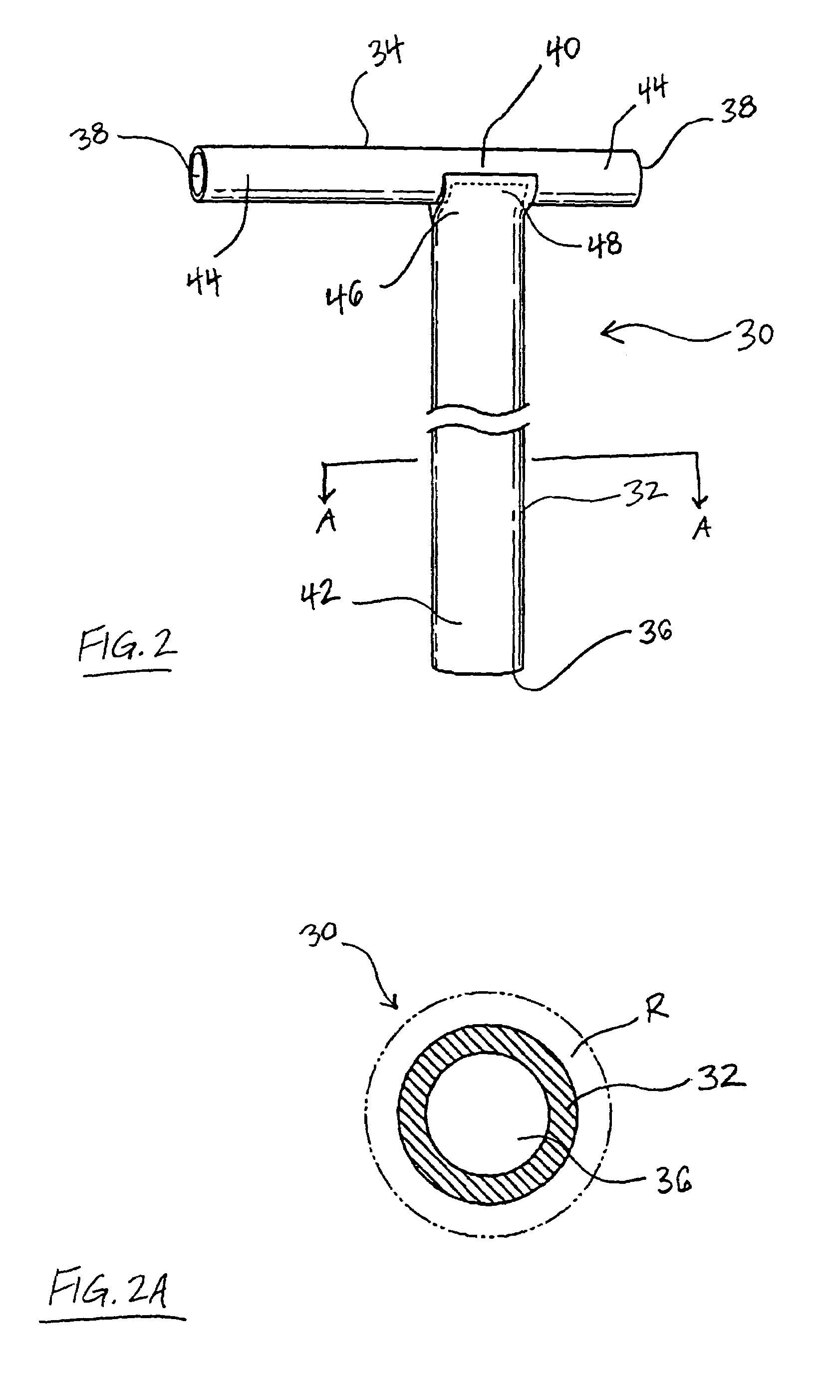
[0010]According to one embodiment of the invention, methods and devices are provided for manufacturing a conduit for use in placing a target vessel in fluid communication with a source of blood. One method includes steps of providing a biocompatible material suitable for use in delivering blood, and forming the biocompatible material into a conduit comprising first and second portions disposed transverse to each other and having lumens in fluid communication. The first conduit portion is formed with at least one inlet configured to be positioned in fluid communication with a heart chamber containing blood, and at least a part of the first conduit portion has sufficient rigidity to prevent collapse during myocardial contraction when disposed in or secured to myocardial tissue. The second conduit portion is formed with at least one outlet configured to be placed at least partially within the lumen of a target vessel in fluid communication with the vessel, and at least a part of the second conduit portion has sufficient resiliency to allow the second conduit portion to substantially conform to the contour of the target vessel.
[0014]Still another method includes steps of forming biocompatible material into a conduit comprising first and second portions disposed transverse to each other and having lumens in fluid communication, forming the first conduit portion with at least one inlet configured to be placed in fluid communication with a heart chamber containing blood, and providing at least a part of the first conduit portion with sufficient rigidity to prevent collapse during myocardial contraction when disposed in or secured to myocardial tissue. The second conduit portion is formed with at least one outlet configured to be placed at least partially within the lumen of a target vessel in fluid communication with the vessel, and this step is carried out so as to form the first conduit portion with a full tubular configuration that extends substantially 360° in cross-section, and the second conduit portion with a partial tubular configuration that extends less than 360° in cross-section.

Problems solved by technology

Despite the considerable advances that have been realized in cardiology and cardiovascular surgery, heart disease remains the leading cause of death throughout much of the world.
Some of the challenges associated with these procedures include delivering and deploying the conduit in the patient's body, and in particular properly positioning the conduit with respect to the heart chamber and the target vessel.

Method used


Image

  • Manufacturing conduits for use in placing a target vessel in fluid communication with a source of blood
  • Manufacturing conduits for use in placing a target vessel in fluid communication with a source of blood
  • Manufacturing conduits for use in placing a target vessel in fluid communication with a source of blood

Examples


example 1

[0110]A first mold including two mold halves was machined from aluminum and had a configuration substantially the same as that shown in FIG. 6. The mold halves were connected via dowel pins and grooves were milled into the faces of the mold halves. The grooves defined a cavity with first and second portions disposed transverse to each other to form a conduit having the same configuration. The first and second cavity portions were sized to receive a steel mandrel, and the cavities and the mandrel substantially corresponded to those shown in FIG. 6

[0111]A light coating of spray-on mold release was applied to the mandrel, and the mandrel was placed in the mold halves which were then assembled. Silicone was used as the moldable material. Air was removed from the silicone by vacuum and ultrasonic agitation prior to injecting the silicone into the mold cavity. Next, approximately one cc of NuSil Med-4950 silicone was poured into the inlet of the mold to form the conduit preform (as this c...

example 2

[0115]Two tubular lengths of expanded PTFE (ePTFE) having a wall thickness of 0.008 inch and an internodal distance of 30 microns were formed substantially as the two conduit portions shown in FIG. 18. Mandrels were coated with a release agent and were used to support the two pieces of ePTFE while they were joined. Silicone was placed between the two portions at the junction and the silicone was cured in an oven at 150° for 2 hours to bond the two portions; the silicone, NuSil Med-6640 wicked between the nodes of the ePTFE and when cured bonded the pieces together to produce a conduit preform having two portions with lumens in fluid communication.

[0116]A reinforcing component was applied by wrapping a nitinol wire around the first and second conduit portions. The exterior surface of the conduit preform was coated with NuSil Med-4850 (LSR) silicone and the reinforcing wire was wrapped around the preform, embedding itself in the silicone. The silicone was then cured again in an oven a...


PUM

PropertyMeasurementUnit
angleaaaaaaaaaa
wall thicknessaaaaaaaaaa

Abstract

Methods and devices for manufacturing a conduit for placing a target vessel in fluid communication with a source of blood, such as a heart chamber containing blood. The conduit includes first and second portion adapted to be placed in fluid communication with a heart chamber and a target vessel. The conduit lies on the exterior of the myocardium between the blood source and the target vessel and delivers blood in multiple directions within the lumen of the target vessel. The conduit, which may be formed of any suitable synthetic vascular graft material, is generally T-shaped with the leg having two free ends disposed in the target vessel, preferably being secured thereto via a suture-free attachment. The conduit comprises vascular graft material and may be manufactured various ways, such as molding a conduit from any suitable biocompatible material or fabricating a conduit from one or more pieces of vascular graft material.

Description

CROSS REFERENCE TO RELATED APPLICATION:[0001]This application is a divisional of U.S. patent application Ser. No. 09 / 314,119, filed May 19, 1999 now U.S. Pat. No. 7,075,937.BACKGROUND OF THE INVENTION[0002]1. Field of the Invention[0003]The invention relates to methods and devices for manufacturing a conduit for placing a target vessel in fluid communication with a source of blood, and more particularly placing a coronary vessel in fluid communication with a heart chamber containing blood.[0004]2. Description of Related Art[0005]Despite the considerable advances that have been realized in cardiology and cardiovascular surgery, heart disease remains the leading cause of death throughout much of the world. Coronary artery disease, or arteriosclerosis, is the single leading cause of death in the United States today. As a result, those in the cardiovascular field continue to search for new and improved treatments.[0006]Coronary artery disease is currently treated by interventional proce...

Claims


Application Information

Patent Timeline
Patent Type & Authority Patents(United States)
IPC IPC(8): B29C65/52B29C41/14B29C45/00B29C45/14
CPCB29C41/14B29C45/0001Y10T156/1062B29K2083/005B29K2995/0056B29C45/14
Inventor RAPACKI, ALAN R.CARSON, DEAN F.SHARKAWY, A. ADAM
Owner MEDTRONIC INC
Learn More