
Making foam coated mats on-line

a technology of foam coating and mats, which is applied in the field of making foam coating mats online, can solve the problems of irritating the hands and arms of workers handling and installing insulating board products, process breakouts adding to production costs, and difficult folding around the edges of boards, etc., and achieves low cup weight, high blow ratio, and low permeability.

Inactive Publication Date: 2007-10-23
JOHNS MANVILLE CORP
View PDF81 Cites 15 Cited by
  • Summary
  • Abstract
  • Description
  • Claims
  • Application Information

AI Technical Summary

Benefits of technology

[0037]The glass fibers can be E, C, A, T, S or any known type glass fiber of good strength and durability in the presence of moisture and mixtures of lengths and diameters. Fibers of any diameter can be used, but the preferred fibers are K 137 (about 13 micron average diameter) or M 137 (about 16 micron average diameter) and 117K or M 117 E glass fibers available from Johns Manville International, Inc. of Denver, Colo., but most commercially wet chop glass fiber products are be suitable. A substantial advantage of the present invention is that it enables the use of larger fiber diameters, which are less expensive, while producing a faced product that has a surface that is “user friendly” and non abrasive. Larger fiber diameters have caused irritation problems in past facer products causing the industry to shift to more costly; smaller diameter fibers like H or G fibers (about 10 or 9 microns average diameter).
[0038]The binder used to bond the fibers together can be any conventional binder capable of bonding the fibers together. A wide variety of binders are used to make nonwovens with urea formaldehyde (UF), acrylic resin, melamine formaldehyde (MF), polyester, acrylics, polyvinyl acetate, and urea formaldehyde and melamine formaldehyde binders modified with polyvinyl acetate and / or acrylic being typically used.
[0039]The foam used to make the foam coating of the two layered mat should not penetrate substantially into the aqueous resin binder slurry, but could penetrate slightly. The foam should have a very high blow ratio (or low cup weight, i.e. grams per liter), the density of the foam precursor divided by the density of the wet froth or foam, forming a very dry froth. The blow ration should be at least 12 and preferably at least 25, most preferably about 15-30 such as 15-18. The foam must be extremely non-draining, for example when a one liter Imhoff cone is filled with the wet froth or foam and allowed to stand for 16 hours, less than 5 millimeters and preferably less than 2 millimeters of liquid should collect in the bottom of the cone. The foam should be rapid breaking when exposed to heat due either to the nature of the resin in the foam or the amount of inert fillers in the foam, and not form an impermeable film during drying. The foam, when it breaks during drying, should have a viscosity of at least 200 centipoise and preferably at least 500 centipoise, with a viscosity in the range of about 200 to about 600 being preferred, so that the broken foam does not penetrate too far into the fibrous web substrate. One suitable foam is TN-599 available from B. F. Goodrich of Brecksville, Ohio Another suitable foam is used in the following example.
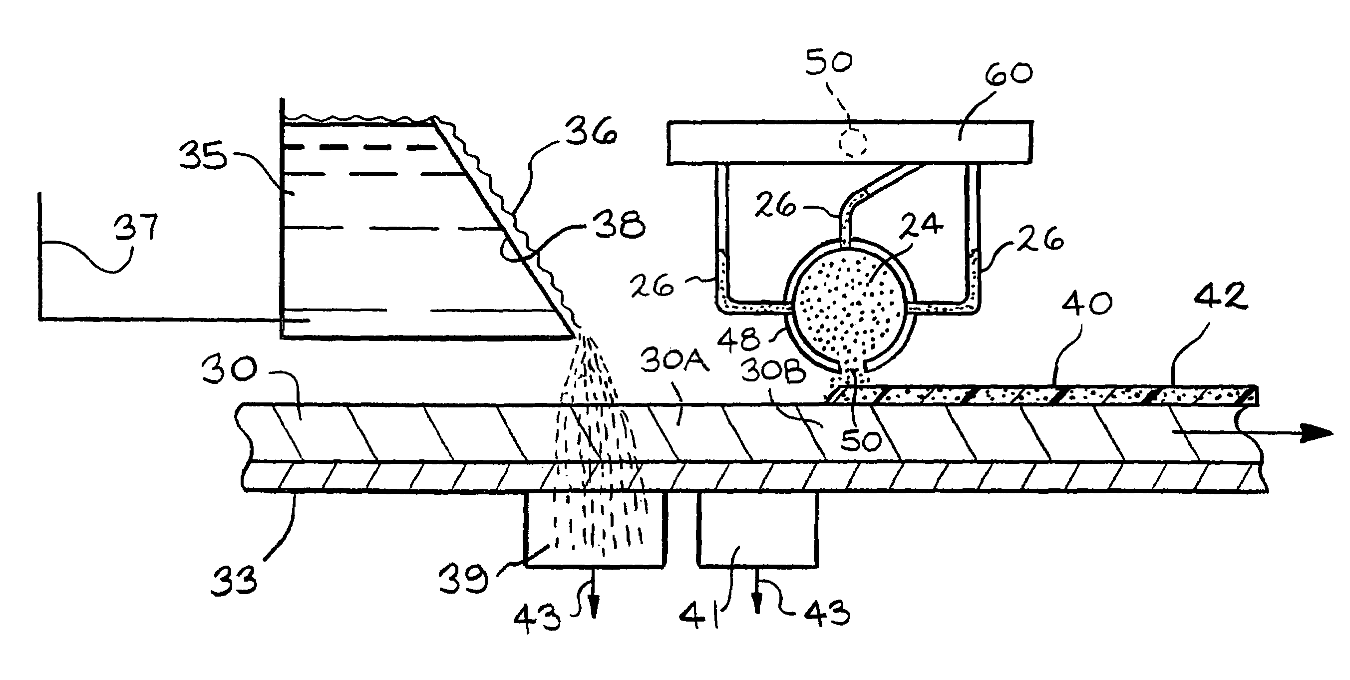
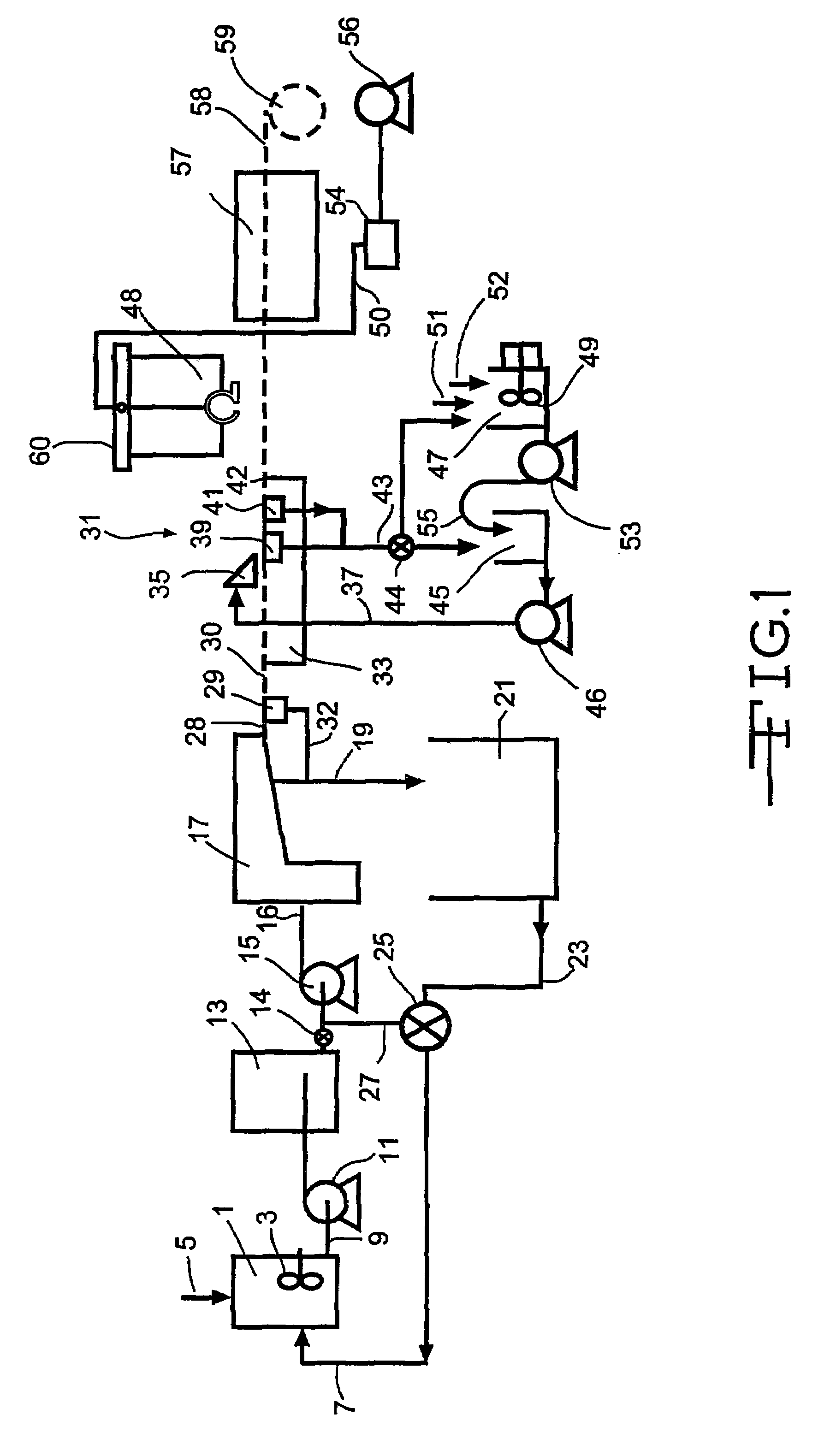
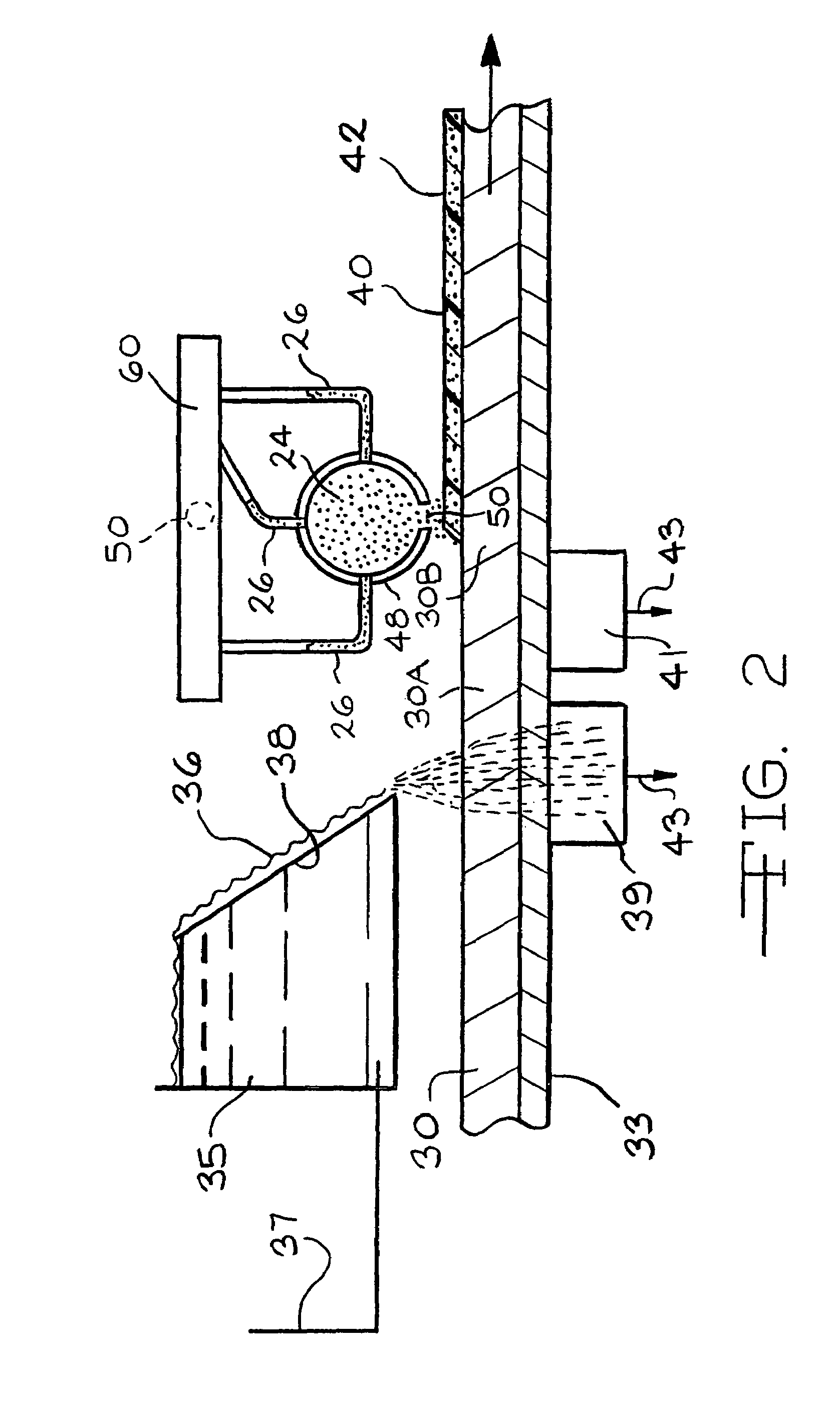
[0040]The type of foam should be selected according to the parameters provided above and the rate of application should be controlled such that the permeability of the foam coated mat is at least 150-200 cubic feet per minute per square foot (CFM / sq. ft.). More preferably the permeability of the foam coated mat is at least 350 and most preferably at least 500 CFM / sq. ft. Where the foam is applied by continuous extrusion, such as in FIGS. 2 and 3, the foam should be applied at a velocity that approximates the linear speed of the wet web for best results. The importance of permeability in the foam coated mat is to allow penetration of the material being used to adhere the foam coated surface to another medium, such as an adhesive used to bond a scrim, decorative facing or other material to the foam coated surface of the mat. Another important consideration in certain applications such as when used to face certain insulation media is that the permeability allows the product to “breath”, i.e. to pass air or other gases through the mat facer. Lower permeability can be preferred if drying is done by can or impingement ovens, rather than with a through air oven.
[0041]FIG. 3 shows another embodiment of applying foam to the wet mat according to the present invention. This embodiment is the same as the embodiment shown in FIG. 2 except for the binder applicator used. In this embodiment, a foam extruder 70 is used, such as a Zimmer Variopress foam applicator available from J. Zimmer Maschinenbau Ges. GmbH of Klagenfurt, Germany. The foam 72, as described above, enters the Variopress foam applicator 70 from above after being pumped in the manner described in the description of FIG. 2 above. The foam 72 flows by gravity down through the foam applicator housing 71 and into two counter rotating gears 73,74, which pump the foam at a desired and controlled rate through an extrusion die 75 and onto the wet, bindered mat 30B to form the foam coating 42. The gear 73 rotates clockwise and the gear 74 rotates counter clockwise. The speed of rotation of the gears 73,74, is variable and can be changed to deliver the desired rate of foam onto the wet, bindered mat 30B according to the linear speed of the wet, bindered mat 30B and the desired coating thickness or foam loading of the foam coating 42. The Variopress foam applicator can be raised and lowered in any suitable manner to optimize the application of the foam onto the wet, bindered mat 30B. The Variopress foam applicator 70 preferably spans completely across the width of the mat 30B, but need not if only a portion of the width of the mat 30B is to be coated with foam.
[0042]FIG. 4 shows a still further embodiment of applying a foam layer onto a wet, bindered non-woven web or mat 30B. This embodiment is similar to the embodiments described in FIGS. 2 and 3, except that the foam is applied using a different-device. In the embodiment shown in FIG. 4 the foam applicator 78 is a counter clockwise rotating perforated drum 79, such as a Zimmer MAGNOROLL™ available from Zimmer Machinery of Spartanburg, S.C. 29304. The perforated drum 79 is made from a 16H perforated metal screen available from Stork Screens of America of Charlotte, N.C. 28269. The screen used has hexagonal shaped holes that are preferably so close together that foam dots formed on the wet, bindered mat 30B from foam extruded through the hexagonal holes flow together to form a continuous layer 42 of foam, although it is also permissible for some applications if the foam hexagonal dots do not quite flow together.

Problems solved by technology

The fiber glass mat (Johns Manville's 7502 Mat-2 lb. / 100 sq. ft.) made using a binder of urea formaldehyde performed good in the process disclosed in U. S. Pat. No. 4,647,496 to make a faced insulating gypsum board, also disclosed in that patent, but the mat was not as strong as desired which caused process breakouts adding to production costs.
This mat was also more rigid than desired which made it difficult to fold around the edges of the board and also irritated the hands and arms of the workers handling and installing the insulating board product.
Further, when the faced insulated gypsum board was cut, the dust from the mat was excessive and further irritated those it contacted, particularly if the workers bare arms, etc. were sweaty and exposed to the dust.
Skin abrasion and irritation was also a problem for those handling the mat and the faced board when not wearing gloves and long sleeve shirts.

Method used


Image

  • Making foam coated mats on-line
  • Making foam coated mats on-line
  • Making foam coated mats on-line

Examples


example 1

[0045]A wet web was formed in a conventional wet process on a laboratory wet former simulating a Voith Hydroformer™ line as used and disclosed in U.S. Pat. Nos. 4,637,496 and 5,772,846 using M 117 glass fibers one inch long. A fiber slurry was prepared in a well known manner by adding one inch long E glass type M 117 wet chop glass fiber from Johns Manville International, Inc. having a silane containing chemical sizing on the surface, as is well known, to a known cationic white water containing Natrosol™ thickening agent available from Aqualon, Inc. of Wilmington, Del., and a cationic surfactant C-61, an ethoxylated tallow amine available from Cytec Industries, Inc. of Morristown, N.J., as a dispersing agent to form a fiber concentration of about 0.8 weight percent. After allowing the slurry to agitate for about 5 minutes to thoroughly disperse the fibers, the slurry was metered into a moving stream of the same whitewater to dilute the fiber concentration to a concentration averagin...

example 2

[0053]Another wet web was formed in the same conventional wet process on a laboratory wet former simulating a Voith Hydroformer™ line as used and disclosed in U.S. Pat. Nos. 4,637,496 and 5,772,846 as used in Example 1. A fiber slurry was prepared in a well known manner by adding 0.75 inch long E glass type K 117 wet chop glass fiber from Johns Manville International, Inc. having a silane containing chemical sizing on the surface, as is well known, to a known cationic white water containing Natrosol™ thickening agent available from Aqualon, Inc. of Wilmington, Del., and a cationic surfactant C-61, an ethoxylated tallow amine available from Cytec Industries, Inc. of Morristown, N.J., as a dispersing agent to form a fiber concentration of about 0.8 weight percent. After allowing the slurry to agitate for about 5 minutes to thoroughly disperse the fibers, the slurry was metered into a moving stream of the same whitewater to dilute the fiber concentration to a concentration averaging ab...

example 3

[0063]Example 2 was duplicated except for the type of foam used and the basis weight of the finished mat which in this example was 1.3 pounds per / 100 sq. ft. Also, a non-foam coated, bindered mat of the same kind as the bindered mat used to make the foam coated mat was made as a control. In this example a fluorpolymer was used. The fluorpolymer used was Sequapel NRL available from Omnova Solutions of Chester, S.C. The properties of fluorpolymer foam coated mat and the control mat were as follows:

[0064]Control mat LOI—27.6 percent

[0065]Foam coated mat LOI—29.1

[0066]Amount of foam addition—about 1.5 wt. percent of finished mat

[0067]Permeability of control mat—643

[0068]Permeability of foam coated mat—620

[0069]Dry tensile strength of control mat—87.1 lbs. / 3 in. width

[0070]Dry tensile strength of foam coated mat—73.1 lbs. / 3 in. width

[0071]Hot wet tensile of control mat—40.3 lbs. / 3 in. width

[0072]Hot wet tensile of foam coated mat—33.9 lbs / 3 in. width

[0073]The foam coated mat was tested f...


PUM

PropertyMeasurementUnit
viscosityaaaaaaaaaa
viscosityaaaaaaaaaa
widthaaaaaaaaaa

Abstract

A new foam coated nonwoven fibrous mat having properties particularly suited for a facer on gypsum wallboard, laminates made therefrom and the method of making the mat is disclosed. The mat preferably contains a major portion of glass fibers and a minor portion of a resinous binder. The foam coating is permeable and reduces fiber dust and abrasion experienced in the past with relatively coarse, relatively inexpensive glass fibers in the mat. Contrary to previous methods, the foam coated fibrous mat is made in-line on a wet mat forming production line by applying a wet foam binder onto a wet, fibrous web followed by drying and curing in-line.

Description

[0001]This application is a continuation of application Ser. No. 11 / 062,980 filed Feb. 22, 2005 now abandoned, which application was a continuation of application Serial No. 10 / 378,438 filed on Mar. 3, 2003, now U.S. Patent No. 6,875,308, which was a division of application Ser. No. 09 / 923,932 filed on Aug. 7, 2001, and now U.S. Patent No. 6,723,670.BACKGROUND OF THE INVENTION[0002]The present invention involves a process of coating a non-woven fiber glass mat with foam or froth on the same wet process line used to make the mat, as an intermediate step in the mat manufacturing process, and the foam coated fiber glass mat products that result. These coated mats have many uses, but are especially useful as a facing on a gypsum wallboard for exterior application and on which stucco is applied.[0003]Fibrous non-woven mats are often formed into a wet mat from an aqueous dispersion of fibers such as glass and / or synthetic organic fibers can include other fibers such as cellulose fibers, c...

Claims


Application Information

Patent Timeline
Patent Type & Authority Patents(United States)
IPC IPC(8): D21H19/70D21H19/44B32B13/14D21H13/40D21H21/56D21H23/28
CPCB32B13/14D21F9/00D21H21/56D21H23/28D21H13/40D21H23/50Y10T428/249958Y10T442/2148Y10T428/249981Y10T442/2139Y10T428/249953Y10T428/249962Y10T428/24999Y10T442/60Y10T442/652Y10T442/647
Inventor KAJANDER, RICHARD EMILJAFFEE, ALAN MICHAELBENNETT, GLENDA B.
Owner JOHNS MANVILLE CORP
Learn More