Spread illuminating apparatus having light coverging means

Inactive Publication Date: 2007-10-23
MINEBEA CO LTD
View PDF8 Cites 5 Cited by
  • Summary
  • Abstract
  • Description
  • Claims
  • Application Information

AI Technical Summary

Benefits of technology

[0010]The present invention has been made in the light of the above problem, and it is an object of the present invention to provide a spread illuminating apparatus, in which light, that is emitted from a light source in directions forming a large angle with respect to major surfaces of a light conductive plate and that is not effectively utilized conventionally, is converged, while passing through an area conventionally called “dead area”, only in a direction orthogonal to the major surfaces of the light conductive plate, whereby the light from the light source is fully and effectively utilized for a brighter illumination with a same power consumption, and at the same time downsizing can be achieved.
[0020]Accordingly, light emitted from the light source in a direction forming a large angle with respect to the major surface of the light conductive plate can be converged while traveling through the light converging means, whereby the light can be fully and effectively utilized thus achieving a brighter illumination with the same level of power consumption.

Problems solved by technology

In the spread illuminating apparatus shown in FIG. 8, however, light emitted from the LED 1 is not fully used.
Here, lights PR have their traveling directions changed to some degree due to the refractive index of the adhesive filled, but not much effectively, so there are still some lights not introduced in the light conductive plate 2, and utilization efficiency of light emitted from the LED 1 remains poor therefore hampering enhancement in brightness as well as reduction in power consumption.
However, the SELFOC lens focuses light entirely toward its optical axis, and is not adapted to converge light only in a particular direction, for example, vertically as shown by Y in FIGS. 6A and 6B.
But, the cylindrical lens has a uniform refractive index profile as described above, and therefore does not provide a good convergence characteristic.
Further, since the cylindrical lens has an aced incidence surface so as to converge diffused light in a parallel manner, an open space still remains toward the LED 1 thus generating reflection loss.
This, however, results in that the refractive index of the cylindrical lens is defined as relative to the refractive index of the filled adhesive or resin therefore significantly deteriorating the converging performance of the cylindrical lens.
A cylindrical lens having a thickness of 1 to 2 mm and formed of glass having a high refractive index may duly work, but to produce such a cylindrical lens is difficult or prohibitive in view of physical strength, manufacturing technology and production cost.
On the other hand, a cylindrical lens formed of synthetic resin does not achieve required performance because the synthetic resin has a lower refractive index than the glass therefore lowering its convergence factor.

Method used


Image

  • Spread illuminating apparatus having light coverging means
  • Spread illuminating apparatus having light coverging means
  • Spread illuminating apparatus having light coverging means

Examples


Embodiment Construction

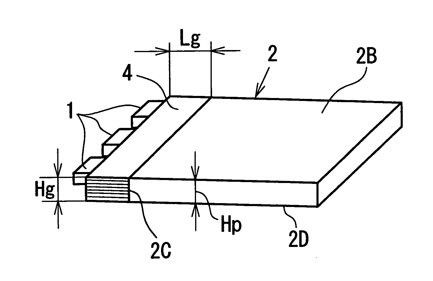
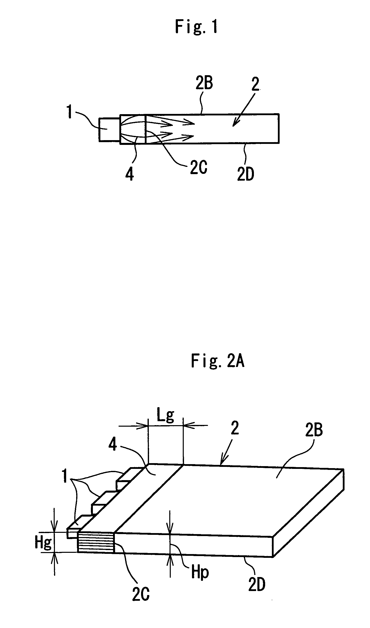
[0031]A preferred embodiment of the present invention will be described with reference to FIGS. 1, and 2A to 2D, together with FIG. 7 as appropriate.

[0032]Referring to FIGS. 1 and 2A, a spread illuminating apparatus of the present invention comprises a light conductive plate 2, a plurality (three in the embodiment) of LED's 1 as light sources, and a light converging element 4 as light converging means. The light converging element 4 is disposed between the LED's 1 and the light conductive plate 2 so as to occupy an area corresponding to the dead area 2A present in the conventional spread illuminating apparatus shown in FIG. 7. The light converging element 4 has a graded refractive index profile in a direction orthogonal to one major surface (light exit surface) 2B of the light conductive plate 2. The light conductive plate 2 is described as having a constant thickness, that is to say the light exit surface 2B is parallel to another major surface (bottom surface) 2D, in the ensuing d...


PUM


Abstract

A spread illuminating apparatus includes a light converging element which has a refractive index profile in a direction orthogonal to two major surfaces of a light conductive plate, and which is disposed between at least one light source and one end surface of the light conductive plate. The light converging element comprises: a plurality of transparent resin films which have respective refractive indexes so as to constitute a refractive index gradation mirror-imaged with respect to the center plane of the light converging element, and which are layered over one another; and a plurality of light-transmittable adhesive layers each of which is sandwiched between two adjacent transparent resin films.

Description

BACKGROUND OF THE INVENTION[0001]1. Field of the Invention[0002]The present invention relates to a spread illuminating apparatus for use with a liquid crystal display device, and more specifically to a spread illuminating apparatus equipped with a means for increasing utilization efficiency of light emitted from a light source.[0003]2. Description of the Related Art[0004]A spread illuminating apparatus of side light type, in which at least one light source is disposed at an end surface of a light conductive plate, is heavily used as a subsidiary illuminating apparatus for a liquid crystal display (LCD) device. A bar-like lamp as a light source, which has a length substantially equal to the longitudinal dimension of an end surface of a light conductive plate, is disposed at the end surface in order to illuminate the light conductive plate entirely in a uniform manner.[0005]In an electronic device, such as a portable telephone, which demands downsizing and lower power consumption, a l...

Claims


Application Information

Patent Timeline
IPC IPC(8): F21V7/04F21V8/00G02B6/00F21Y101/02G02F1/13357H04M1/22
CPCG02B6/0028Y10S385/901H04M1/22
Inventor KITAMURA, ATSUSHISUZUKI, SHINGO
Owner MINEBEA CO LTD
Why Eureka
Try Eureka