
Recording/reproducing head

a recording/recording head technology, applied in the field of recording/recording head, can solve the problems of large probe size, complicated assembly, limited recording density, etc., and achieve the effect of simple structure, easy production, and suitable mass production

Inactive Publication Date: 2007-10-16
PIONEER CORP +1
View PDF49 Cites 9 Cited by
  • Summary
  • Abstract
  • Description
  • Claims
  • Application Information

AI Technical Summary

Benefits of technology

[0009]It is therefore an object of the present invention to provide a recording / reproducing head for recording / reproducing data in / from a dielectric recording medium, having a simple structure, easy to produce, and appropriate for mass-production, as well as a method of producing the recording / reproducing head.
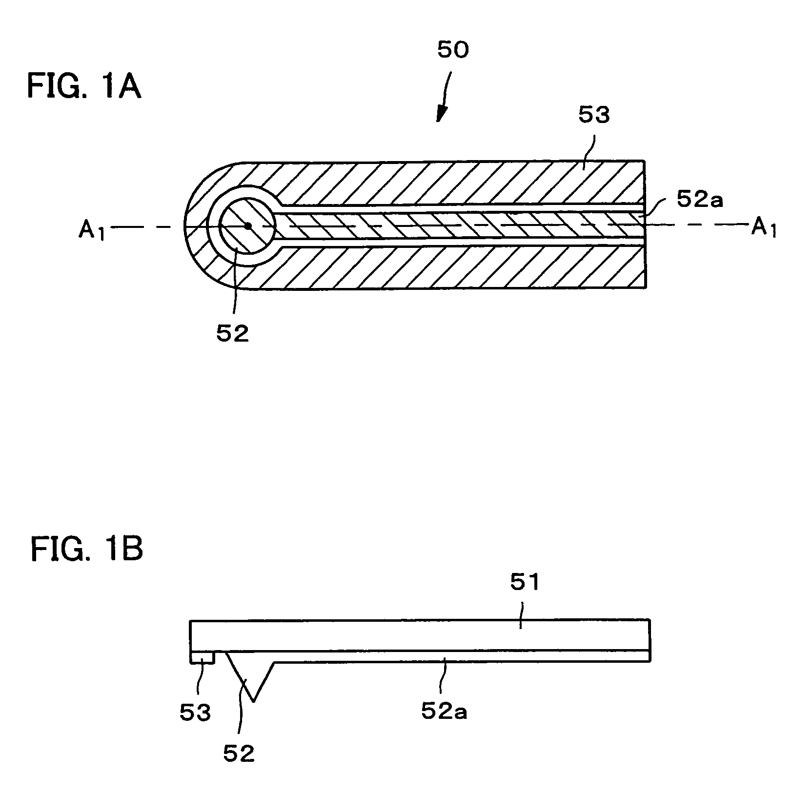
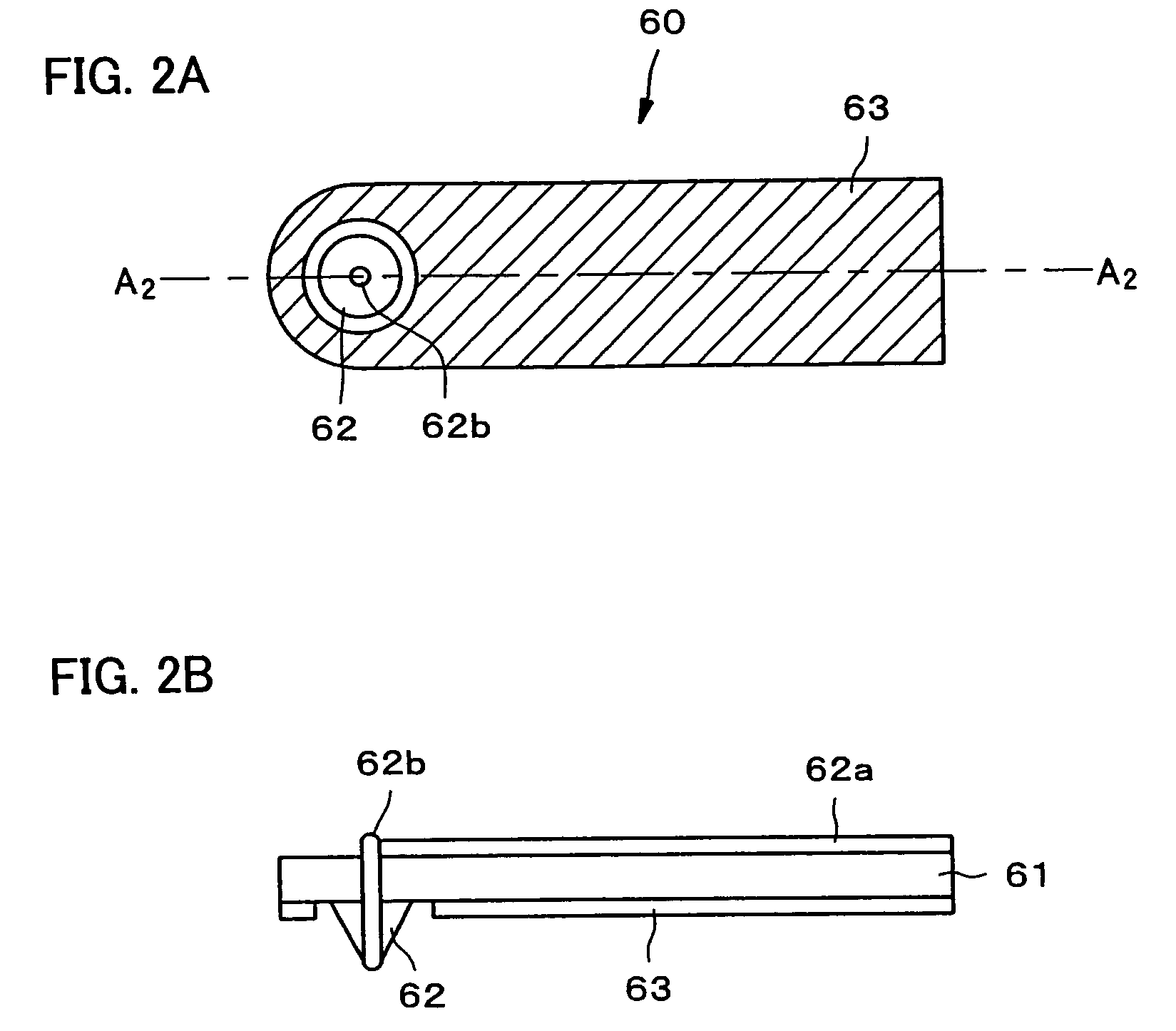
[0011]According to the recording / reproducing head of the present invention, the first electrode is formed on the supporting member. The supporting member is, for example, in the shape of a cantilever. The first electrode is an electrode for applying an electric field to the dielectric recording medium for recording / reproducing the information. More concretely, on one end of the supporting member, which contains Si, for example, there is a projection portion which will be a probe, and the surface of the projection portion is provided with a conductive film thereon. A lead wire, which is connected with the conductive film, is disposed on a surface of the supporting member with the projection portion thereon in the direction to the other end. Moreover, another conductive film is disposed so as to surround the probe and the lead wire with a space or gap. This conductive film is a return electrode for returning a high-frequency electric field applied to the dielectric recording medium from the probe. According to this recording / reproducing head having such a construction and shape, the tracing capability of the probe improves.
[0016]On the other hand, a conductive film is disposed on the surface of the supporting member facing to the dielectric recording medium so as to surround the probe with a space or gap. This conductive film is a return electrode for returning a high-frequency electric field applied to the dielectric recording medium from the probe. According to the recording / reproducing head having such a construction and shape, the tracing capability of the probe improves.
[0018]According to the recording / reproducing head of the present invention, the substrate is in such a shape that has the supporting member and a ring-shaped member. The supporting member is, for example, in the shape of a cantilever, and is provided with a probe for recording / reproducing thereon. The ring-shaped member surrounds the supporting member with a space or gap, and has a part that fixes one end of this supporting member. As the substrate, Si may be used, for example. A conductive film is disposed on the surface of the probe, and a lead wire, which is connected with the conductive film, is disposed on the surface of the substrate facing to the dielectric recording medium. Moreover, another conductive film is disposed on the surface facing to the dielectric recording medium so as to surround the probe and the lead wire. This conductive film is a return electrode for returning a high-frequency electric field applied to the dielectric recording medium from the probe. According to the recording / reproducing head having such a construction and shape, the tracing capability of the probe improves. Using the ring-shaped member of the substrate, it is possible to fix this to a trace mechanism.
[0022]On the other hand, a conductive film is disposed on the surface of the supporting member facing to the dielectric recording medium so as to surround the probe with a space or gap. This conductive film is a return electrode for returning a high-frequency electric field applied to the dielectric recording medium from the probe. According to the recording / reproducing head having such a construction and shape, the tracing capability of the probe improves.
[0024]According to this aspect, the SNDM technique is applied, especially to reproducing. The SNDM reproduction technique is introduced in detail by the present inventor, Yasuo Cho, in Oyo Butsuri Vol. 67, No. 3, p327 (1998). Alternatively, it is also described in detail in Japanese Patent Application No. 2001-274346 and No. 2001-274347, etc., filed by the present inventors. Namely, in this technique, data or information is recorded in the dielectric (ferroelectric) material of the dielectric (ferroelectric) recording medium as states of the polarization of the dielectric (ferroelectric) substance. A probe scans over a dielectric (ferroelectric) material to detect the polarization states of the dielectric (ferroelectric) substance. The capacitance of the dielectric (ferroelectric) material located just under the tip of the probe is detected. This capacitance corresponds to a nonlinear dielectric constant of the dielectric (ferroelectric) substance at this part. The nonlinear dielectric constant is determined according to the polarization direction of the dielectric (ferroelectric) substance located just under the tip of the probe. Since data or information is recorded as the polarization states (more concretely, directions of the polarization of the dielectric (ferroelectric) material), the nonlinear dielectric constant corresponds to the recorded data. Namely, the capacitance of the dielectric (ferroelectric) material just under the tip of the probe corresponds to the recorded data. Therefore, the recorded data can be reproduced by detecting the capacitance of the dielectric (ferroelectric) material just under the tip of the probe. The data can be recorded by applying an electric field to the dielectric (ferroelectric) substance from the probe, or from the lower electrode formed in the dielectric (ferroelectric) substance in such a way that the polarization directions are set according to the data or information. By using SNDM, extremely high-density recording becomes possible. Incidentally, the probe is not limited to single use, such as the one for recording or the one for reproducing, but may be sharable as the one for recording and reproducing.

Problems solved by technology

However, the pickup is large and is not appropriate for high-speed reading, and the size of the recording pit is defined by the diffraction limit of light, so that its recording density is limited to 50 G bit / inch2.
However, the recording density is limited to 1 T bit / inch2 due to thermal fluctuation of magnetic recording information and the presence of a Bloch wall in a code reverse or sign change portion, even if patterned media are used considering the above cause.
However, the above-described SNDM has not been specially developed in view of a recording / reproducing apparatus and thus have such a problem that the probe is large or that assembling is complicated.
Moreover, if it has a plurality of probes in order to increase a data transfer rate, the complication increases more.

Method used


Image

  • Recording/reproducing head
  • Recording/reproducing head
  • Recording/reproducing head

Examples


fourth embodiment

of Recording / Reproducing Head

[0067]The fourth embodiment of the recording / reproducing head associated with the present invention will be explained with reference to FIG. 4A and FIG. 4B. FIG. 4A is a plan view of the forth embodiment of the recording / reproducing head associated with the present invention. FIG. 4B is an A4-A4 cross sectional view of FIG. 4A.

[0068]As shown in FIG. 4A and FIG. 4B, a recording / reproducing head 80 associated with the present invention is provided with: a substrate 81 which has a predetermined width and a predetermined thickness. The substrate 81 has a portion to form a cantilever 85 which is long in one direction and a portion which surrounds the cantilever 85.

[0069]In the substrate 81, the portion surrounding the cantilever 85 is in the shape of a ring. A probe 82 is disposed on one end of the cantilever 85 and the other end is fixed to the ring-shaped portion.

[0070]In the central portion of the probe 82, there is provided a hole piercing from the tip po...

first embodiment

of Method Of Producing Recording / Reproducing Head

[0073]The first embodiment of the method of producing the recording / reproducing head associated with the present invention will be explained with reference to FIG. 5A to FIG. 5C. This embodiment is about a method corresponding to the production of the recording / reproducing head 70, for example, and is also applicable to the recording / reproducing head 50.

[0074]FIG. 5A shows a process of forming the probe 72 on the substrate 71 by accumulating a projection portion on the Si substrate or etching the surrounding of the projection portion with the portion left, for example.

[0075]FIG. 5B shows a process, which follows FIG. 5A, of removing the surrounding of the cantilever 75 on the substrate 71 so as to form the cantilever 75 which supports the projection portion. The substrate 71 is in the ring shape to fix thereto one end opposite to the projection portion held by the cantilever 75. The cantilever 75 fixed to the substrate 71 moves vertic...

second embodiment

of Method of Producing Recording / Reproducing Head

[0078]The second embodiment of the method of producing the recording / reproducing head associated with the present invention will be explained with reference to FIG. 6A to FIG. 7F. This embodiment is about a method corresponding to the production of the recording / reproducing head 80, for example, and is also applicable to the recording / reproducing head 60.

[0079]FIG. 6A shows a process of forming the probe 82 on the substrate 81 by accumulating a projection portion on the Si substrate or etching the surrounding of the projection portion with the portion left, for example.

[0080]FIG. 6B shows a process, which follows FIG. 6A, of removing the surrounding of the cantilever 85 on the substrate 81 so as to form the cantilever 85 which supports the projection portion. The substrate 81 is in the ring shape to fix thereto one end opposite to the projection portion held by the cantilever 85. The cantilever 85 fixed to the substrate 81 moves verti...


PUM


Abstract

A recording / reproducing head is provided with: a substrate which has a predetermined width and a predetermined thickness and which is long in one direction; a probe disposed on one end in the longitudinal direction of the substrate; a lead wire disposed on a surface of the substrate provided with the probe thereon, i.e. the lead wire disposed on a surface facing to the dielectric recording medium; and an electric conductor, i.e. a return electrode, disposed so as to surround the probe and the lead wire. The probe is covered with a conductive film as well as connected with the lead wire. Via the lead wire, a signal for recording is inputted from an external device or a signal for reproducing is led to an external device.

Description

BACKGROUND OF THE INVENTION[0001]1. Field of the Invention[0002]The present invention relates to a recording / reproducing head for a dielectric recording medium, for recording information in microdomains in a dielectric substance of the dielectric recording medium and for reproducing information recorded in the dielectric recording medium, and relates to a method of producing the recording / reproducing head.[0003]2. Description of the Related Art[0004]As high-density, large-capacity recording / reproducing apparatuses of randomly accessible type, there are known an optical disk apparatus and a hard disc drive (HDD) apparatus. Moreover, a recording / reproducing technique using a scanning nonlinear dielectric microscopy (SNDM) for the nanoscale analysis of a dielectric (ferroelectric) material has been recently proposed by the inventors of the present invention.[0005]In optical recording, an optical pickup with a laser as a light source is used. Data is recorded by forming pits that are co...

Claims


Application Information

Patent Timeline
IPC IPC(8): G11B9/00B81B3/00B82B3/00G01Q60/00G01Q60/40G01Q60/48G01Q80/00G01Q90/00G11B9/02G11B9/08G11B9/12G11B9/14
CPCB82Y10/00G11B9/02G11B9/1409G11B9/08G11B9/14
Inventor ONOE, ATSUSHICHO, YASUO
Owner PIONEER CORP
Learn More