
Multi-level mapping of tape error recoveries

a technology of error recovery and tape head, applied in the field of recording and retrieval of digital information on magnetic tape, can solve problems such as data errors, media defects, debris between the tape head and the media,

Active Publication Date: 2007-10-09
GOOGLE LLC
View PDF8 Cites 29 Cited by
  • Summary
  • Abstract
  • Description
  • Claims
  • Application Information

AI Technical Summary

Benefits of technology

The present invention provides a method, system, and computer program product for presenting detailed information about successful error recoveries during the recording and retrieval of digital information on magnetic tape. The method includes mapping the successful error recovery information to the physical location on the tape, and generating two output reports with different levels of detail. The system includes an error recovery controller, an error recovery logger, and a report generator. The computer program product includes computer-readable code for mapping error corrections in a magnetic tape drive data storage system, and presenting recovery methods by data band and wrap. The invention allows for pattern analysis and failure pattern identification, which can be used to improve the design of the drive and microcode.

Problems solved by technology

Events which can lead to data errors include defects on the media, debris between the tape head and the media, and other conditions that interfere with head / media data transfer operations.
The presence of data errors is detected when the encoded structure is disturbed.
Error recovery occurs when ECC error correction is unable to correct data errors or when thresholds for allowable error correction are exceeded.
The error recovery process may require stopping the tape and reprocessing a data block in which an error was detected.
However, with the increasing design sophistication required to accomplish ever increasing data densities on the tape, there is a corresponding increasing reliance on complex recoveries and optimization performed internally by microcode, some of which may not be visible and therefore not available for analysis.

Method used


Image

  • Multi-level mapping of tape error recoveries
  • Multi-level mapping of tape error recoveries
  • Multi-level mapping of tape error recoveries

Examples


Embodiment Construction

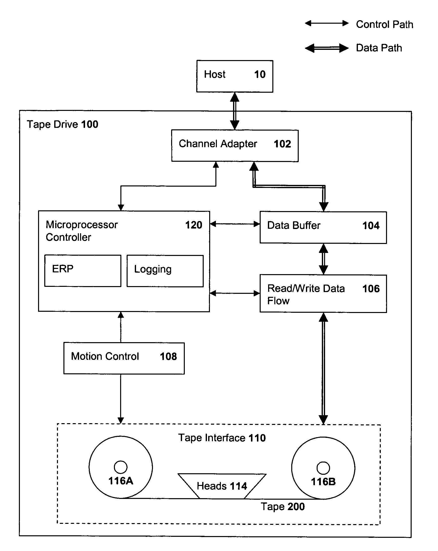
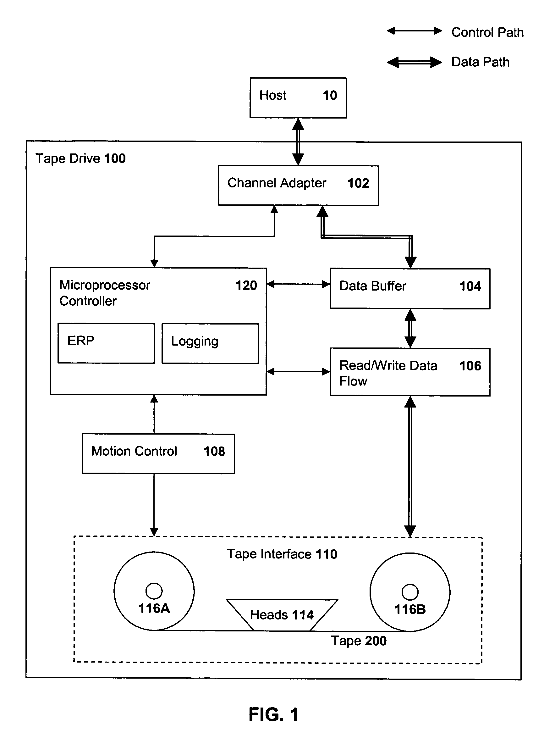
[0015]FIG. 1 is a block diagram of a magnetic tape drive 100 in which the present invention may be incorporated. The tape drive 100 is coupled to a host device 10 through a channel or host adapter 102 from which the drive 100 receives data to be stored to, and transmits data read from, magnetic tape 200. The tape drive 100 further includes a data path and a control path. The data path includes a data buffer 104, coupled to receive data from and send data to the adapter 102, and read / write data flow circuitry 106, coupled between the buffer 104 and a tape interface system 110. The control path includes a microprocessor controller 120, coupled to receive control signals from, and send control and response signals to, the host device 10 through the adapter 102, and a motion control circuitry 108, coupled between the microprocessor controller 120 and the tape interface system 110.

[0016]The microprocessor controller 120 provides overhead control functionality for the operations of all ot...


PUM

PropertyMeasurementUnit
structureaaaaaaaaaa
densitiesaaaaaaaaaa
physicalaaaaaaaaaa

Abstract

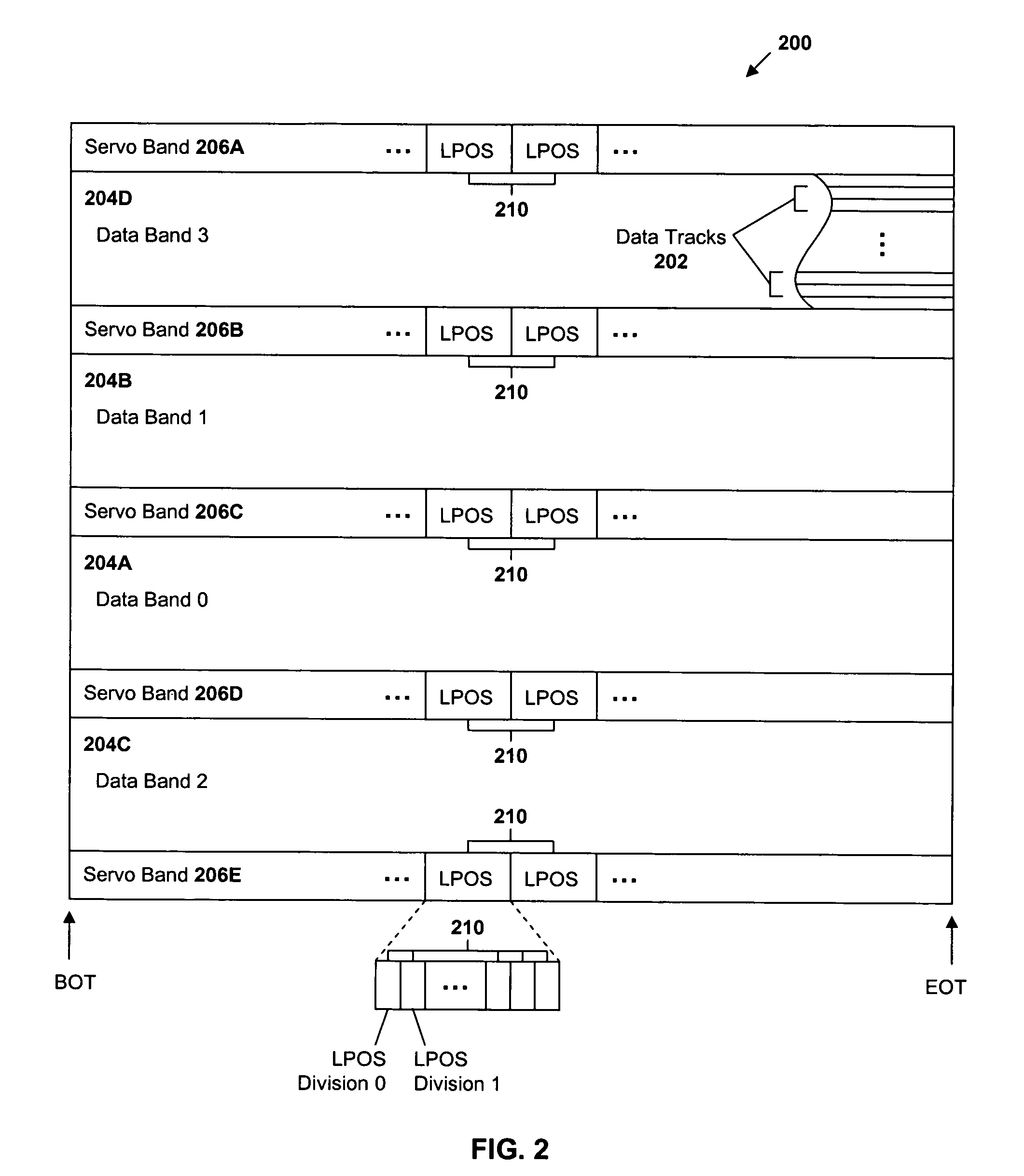
Method and apparatus are provided for presenting various levels of detail about successful error recoveries and background hardware optimizations during the recording and retrieval of digital information on magnetic tape. A first, Band Summary, report presents a high-level summary of recovery methods by data band and wrap. A second, Detail Summary, report presents a mid-level summary of recovery methods by track and longitudinal position (LPOS) region within one wrap of a band on the tape. A third, ERP Summary, report presents a low-level summary of errors and specific recovery methods and optimizations by LPOS region within each wrap. Such “telescoping” views permit pattern analysis to be performed at different resolutions. Thus, correlations of possible interactions between hardware and microcode activities that result in changes of the nominal operating point of the drive may be identified. Possible failure patterns may also be identified and fed back to design personnel and incorporated in microcode design changes for more effective ERP.

Description

TECHNICAL FIELD[0001]The present invention is directed generally to the recording and retrieval of digital information on magnetic tape and, in particular, to providing various levels of detail about successful error recoveries.BACKGROUND ART[0002]Conventional data storage tape drives employ various error correction and recovery methods to detect and correct data errors which, if left unresolved, would compromise the integrity of information read from or written to the magnetic tape media. Events which can lead to data errors include defects on the media, debris between the tape head and the media, and other conditions that interfere with head / media data transfer operations.[0003]Error correction and recovery may be thought of as two distinct operations that are employed at different stages of error processing. Error correction is conventionally implemented using error correction coding (ECC) techniques in which host data to be placed on a tape medium is encoded in a well-defined st...

Claims


Application Information

Patent Timeline
Patent Type & Authority Patents(United States)
IPC IPC(8): G11B27/36G11B5/09
CPCG11B20/1879G11B27/36G11B2220/90
Inventor NYLANDER-HILL, PAMELA RGALE, ERNEST S
Owner GOOGLE LLC
Learn More