
Measurement system with an optical measurement arrangement

Inactive Publication Date: 2007-10-02
VISTEC SEMICON SYST JENA
View PDF13 Cites 0 Cited by
  • Summary
  • Abstract
  • Description
  • Claims
  • Application Information

AI Technical Summary

Benefits of technology

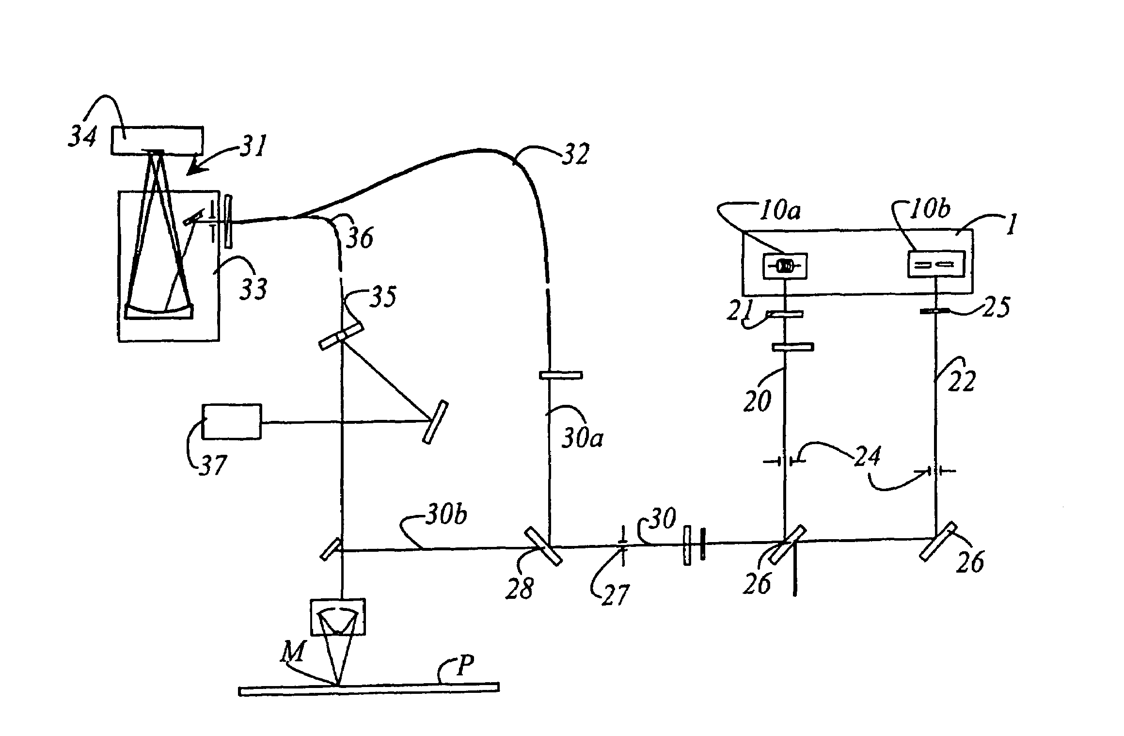
[0010]It is thus the object of the invention to develop further an optical measurement arrangement so as to make possible replacement of the illumination sources in a manner that is more economical and less time-consuming for the user than with hitherto known optical measurement arrangements.
[0014]Instead of replacing only one lamp, the entire lamp housing—which often also contains two lamps (a halogen and a deuterium lamp) in order to cover the widest possible spectrum—is replaced. The new lamp housing can then immediately be connected via the installation element to the remaining portion of the measurement arrangement. The lamps in this lamp housing have already been prealigned, so that in this case alignment is no longer necessary. The measurement arrangement is therefore ready for use again in a very short time. The prealignment can be accomplished, for example, at the premises of the manufacturer or of a company having a maintenance contract.
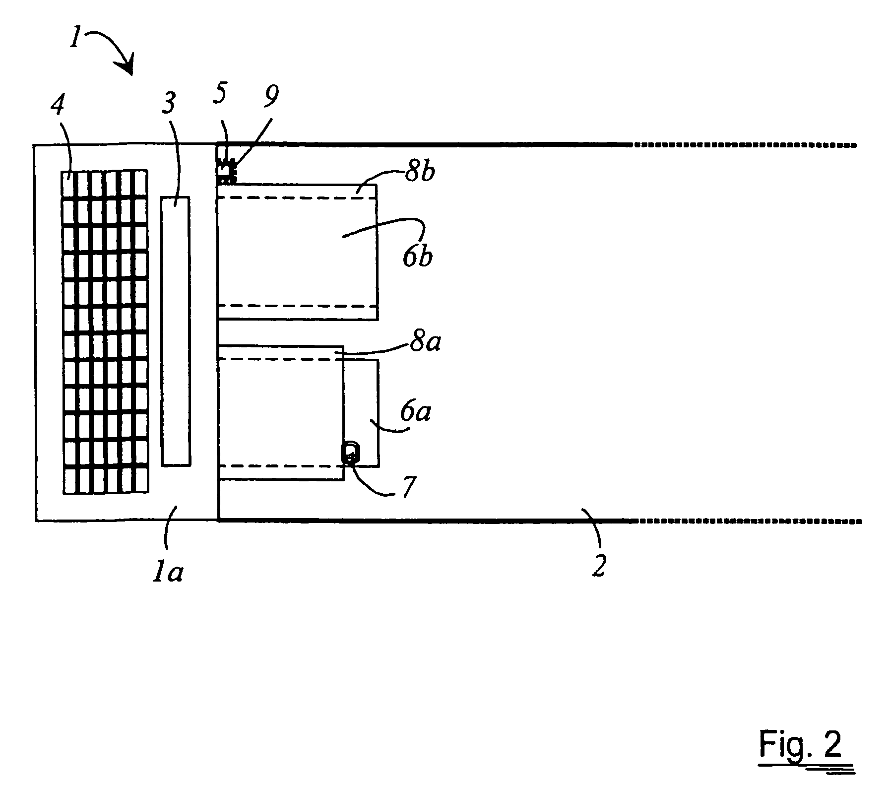
[0016]In order simplify connection to and detachment from the remaining portion of the measurement arrangement, a notch and a stop are preferably provided on the installation element. Two sockets are mounted on the lamp housing, of which one coacts with the notch and the other with the stop. With this, a guidance system that is configured e.g. as a plain guide is implemented immediately upon insertion of a new lamp housing. In this fashion the connection can be very easily made and equally easily unmade again.
[0017]In an advantageous embodiment of the invention, a first contact in the form of a socket and a second contact in the form of a pin are provided in order to create an electrical contact between the lamp housing and the remaining portion of the measurement arrangement. This integration of the electrical contacts into the coupling device makes it possible to dispense with a separate cable for the lamp housing, which makes the lamp housing easier to handle.
[0018]It is advisable for at least one socket of the lamp housing to be equipped with a pin that coacts with a surface of the installation element. This results in a further positional retention of the lamp housing.
[0021]To minimize the number of connecting and structural elements required, it is useful to configure the pin as a hollow cylinder, open at both ends, for transmission of the light proceeding from the illumination source.

Problems solved by technology

The service life of the lamps is limited, however, and as they age they become unsuitable for measurement purposes and must be replaced after a certain time.
Replacement of the lamps must normally be accomplished at the site of the measurement arrangement by technicians of the manufacturer or a maintenance company, since a newly installed lamp must first be aligned with respect to the beam path in a complex operation; the reason is that a lamp that is even slightly misaligned can considerably degrade the performance of the measurement arrangement.
For the customer, this on the one hand is very time-consuming because the time period from failure of the lamp to notification of the technician (possibly not available locally) and alignment of the new lamp is in some circumstances very long, and during that period the lamp cannot be used.
On the other hand, this type of lamp replacement is very cost-intensive.
This apparatus is, however, very expensive to acquire and is susceptible to failure because of its complex mechanism.
No particularly stringent requirements in terms of illumination or alignment of the optics are imposed in these arrangements, however, since the light is not used for measurements and the arrangements thus react less sensitively to slight misalignments.

Method used


Image

  • Measurement system with an optical measurement arrangement
  • Measurement system with an optical measurement arrangement
  • Measurement system with an optical measurement arrangement

Examples


Embodiment Construction

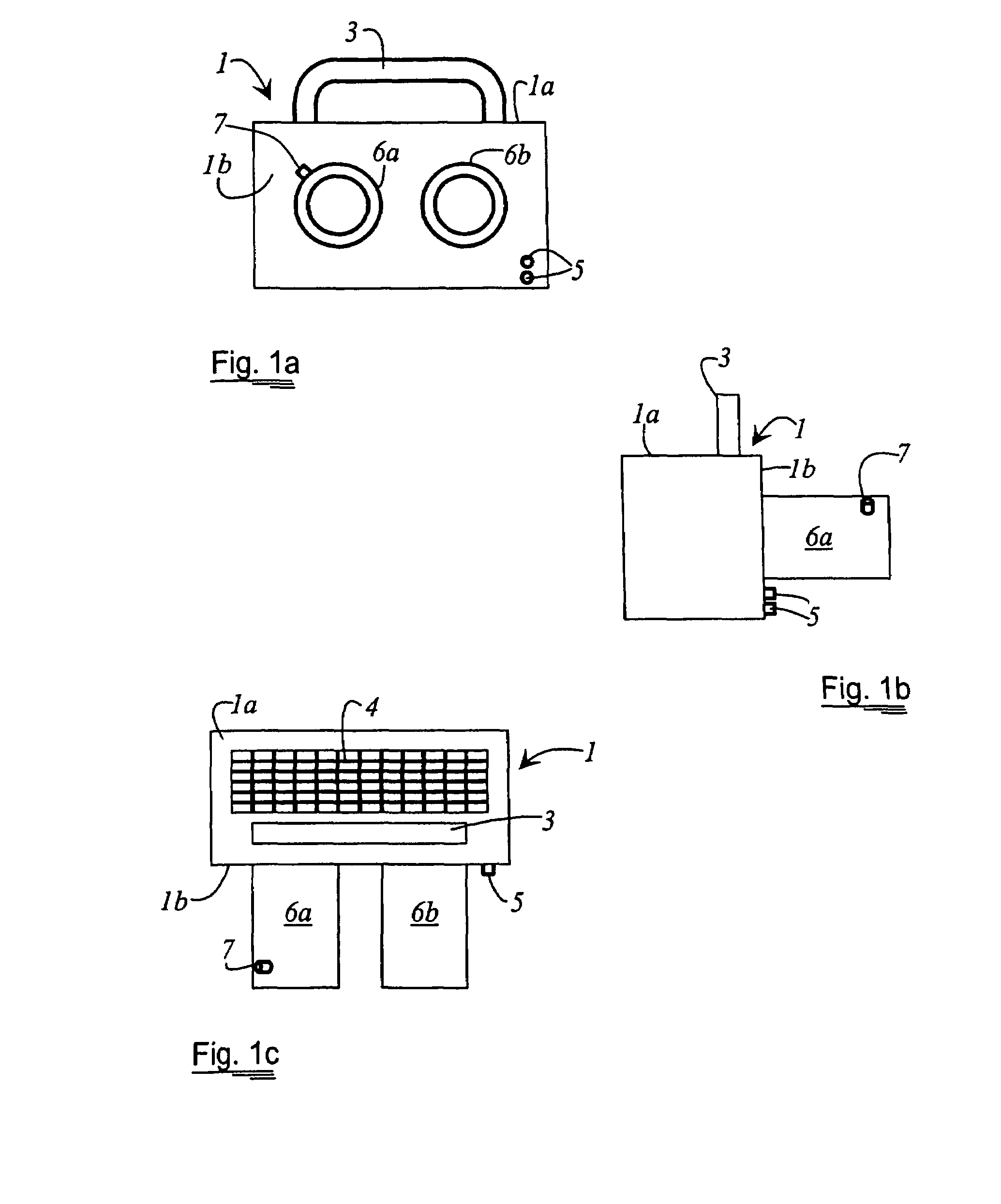
[0033]FIG. 1a is a front view of lamp housing 1, i.e. showing the side that, in the connected state, faces toward remaining portion 2 (cf. FIG. 2) of the measurement arrangement. FIG. 1b is a side view of lamp housing 1, and FIG. 1c a plan view of lamp housing 1. A handle 3 is mounted on an upper side 1a of lamp housing 1 to improve handling and transportability. Also provided on the upper side of lamp housing 1 is a ventilation grid 4 to discharge the heat that is produced during operation of the illumination sources (not depicted) provided in the interior of lamp housing 1.

[0034]Additionally mounted on a front side 1b of lamp housing 1 is at least one contact 5 in the form of a pin, for creating an electrical contact between lamp housing 1 and remaining portion 2 of the measurement arrangement. First and second hollow cylinders 6a and 6b are moreover connected to front side 1b of lamp housing 1. Through hollow cylinders 6a and 6b, light is transmitted from two illumination sources...


PUM


Abstract

The invention concerns an optical measurement arrangement, in particular for the examination of layer systems, and can include an illumination device having at least one illumination source for delivering a measurement light beam and coupling the measurement light beam into the beam path of a layer thickness measuring instrument. In such a measurement arrangement, the illumination device can be housed in a lamp housing that may be detachably connected to the remaining portion of the measurement arrangement via an installation element wherein illumination sources can be prealigned with respect to the beam path.

Description

CROSS REFERENCE TO RELATED APPLICATIONS[0001]This application claims priority of the German patent application 103 09 033.9 which is incorporated by reference herein.FIELD OF THE INVENTION[0002]The invention refers to an optical measurement arrangement defining at least one illumination beam path, in particular for the examination of systems of thin layers.BACKGROUND OF THE INVENTION[0003]High reliability is essential in instruments that are used for dimensional consistency monitoring in continuous fabrication lines—for example, for layer thickness measurement in the context of wafer manufacture in semiconductor production—since information about product quality and the stability of the production process is obtained on the basis of the measurement results. This requires that the accuracy of the measuring instrument technology used be stable.[0004]Fundamentally, the accuracy of optical measurement arrangements depends to a considerable degree on consistent parameters of the measurem...

Claims


Application Information

Patent Timeline
IPC IPC(8): G01B11/28B60Q3/04F21V1/00F21V11/00F21V15/00G01N21/86G01V8/00G01B11/06G01N21/88G01N21/95
CPCG01B11/0625G01N21/9501G01N21/8806
Inventor SLODOWSKI, MATTHIASWOLTER, DETLEF
Owner VISTEC SEMICON SYST JENA
Learn More