
Adaptive bandwidth control in a kinescope amplifier

a technology of adaptive bandwidth control and kinescope amplifier, which is applied in the direction of instruments, television systems, color signal processing circuits, etc., can solve the problems of increasing the power consumption of the video output amplifier in the tv monitor display, easily exceeding 5 watts, and the total power consumption of the display, so as to reduce the power consumption

Inactive Publication Date: 2007-10-02
THOMSON LICENSING SA
View PDF8 Cites 7 Cited by
  • Summary
  • Abstract
  • Description
  • Claims
  • Application Information

AI Technical Summary

Benefits of technology

[0007]In an advantageous circuit arrangement the bandwidth of the video output stage is continuously adjusted in accordance with to the bandwidth requirement or spectral components present or expected in the input signal. As a result, power consumption is reduced when displaying video signals of lower resolution. In a further arrangement, the bandwidth can be adaptively switched between two bandwidth values, normal and wide, by a control signal. This adaptive bandwidth control can be generated by a micro-controller by extracting bandwidth-related data from the video signal or input signal selection.

Problems solved by technology

The power consumption of a video output amplifier in the TV monitor display increases with the bandwidth required to faithfully display the non-broadcast signal bandwidth and amplitude.
However, in a high bandwidth active load amplifier this can easily exceed 5 Watts.
Because a cathode ray tube receiver monitor contains three video output amplifiers these can represent a significant contribution to the total power consumption of the display.
However such dynamic enhancement control is unlike the objectives herein which adaptively control amplifier bandwidth to be sufficient for the actual display signal present at the amplifier input.

Method used


Image

  • Adaptive bandwidth control in a kinescope amplifier
  • Adaptive bandwidth control in a kinescope amplifier
  • Adaptive bandwidth control in a kinescope amplifier

Examples


Embodiment Construction

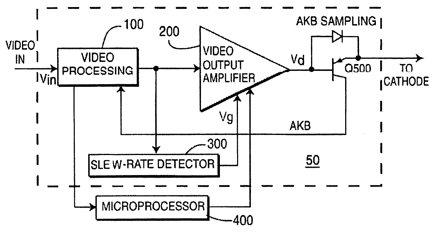
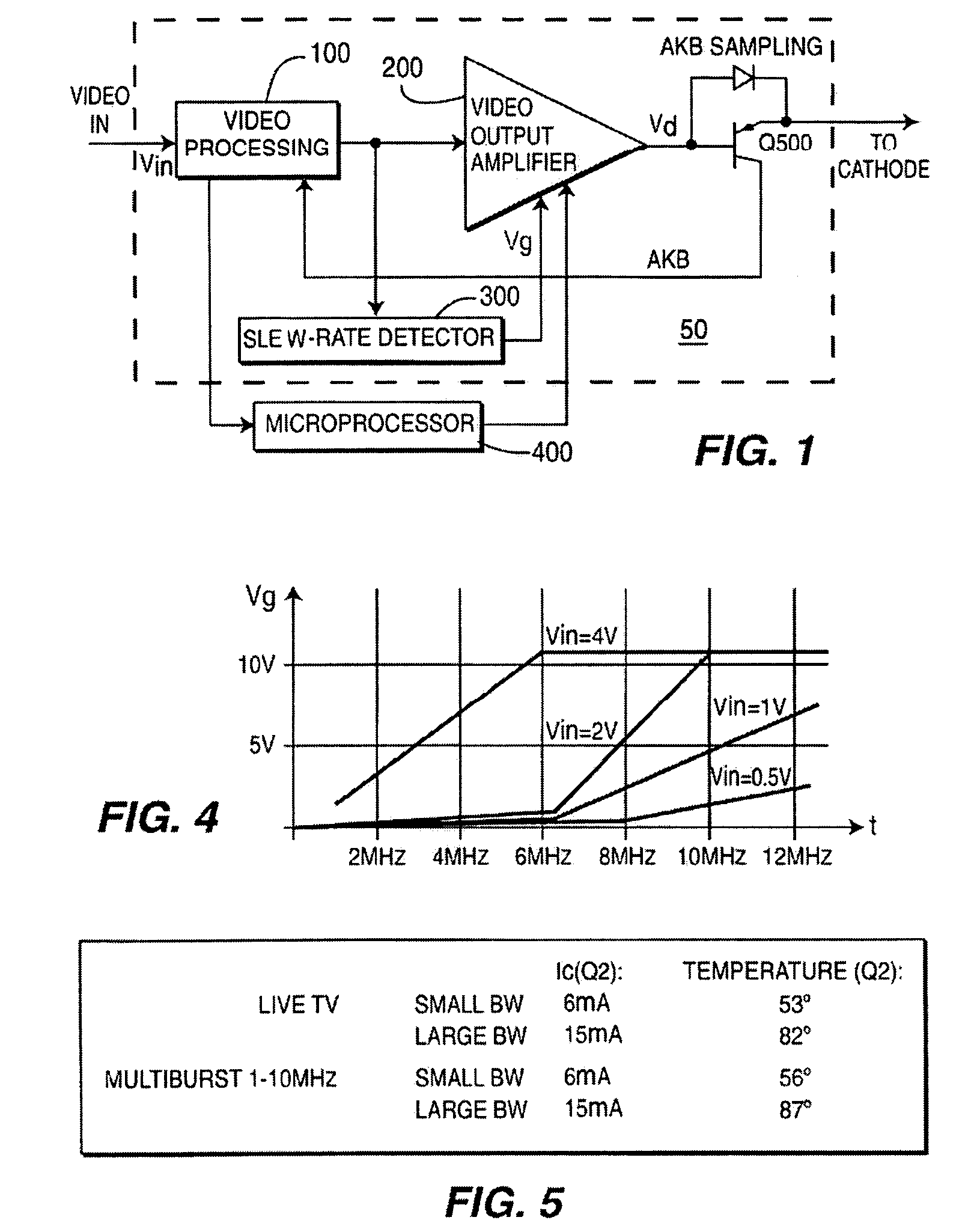
[0016]The block diagram shown in FIG. 1 depicts a cathode ray tube drive amplifier including various inventive arrangements wherein the amplifier bandwidth is adaptively controlled in accordance with the spectral content of the signal to be displayed. In a color cathode ray tube display blocks 100, 200, 250, 400 and 500 are present for each display color, however, microprocessor controller 400 can provide color specific control signals for each color channel. A color display signal, for example red green or blue from, from an exemplary color demodulator or external base band source is input to video processing block 100 for amplification and, for example, DC bias control. Control of the DC content or component of a display signal by means of an automatic kinescope bias or (AKB) feed back control loop is well known and serves to maintain a predetermined current at each cathode of a cathode ray tube display.

[0017]Processing block 100 supplies a color display signal, for example red gr...


PUM


Abstract

A method for controlling dissipation in a video amplifier for a display signal. The method comprises the steps of setting a first current for establishing a first gain bandwidth product in the video amplifier. Generating a control signal in accordance with a slew rate of the display signal. Modifying the first current responsive to the control signal such that the video amplifier gain bandwidth product is controlled in accordance with the slew rate of said display signal.

Description

[0001]This application claims the benefit under 35 U.S.C. § 365 of International Application PCT / EP02 / 09292 filed Aug. 20, 2002, which claims the benefit of U.S. Provisional Application No. 60 / 314,376 filed Aug. 23, 2001.[0002]This invention relates to the field of video display technology and in particular to the dynamic control of power dissipation in accordance with the spectral content of the display signal.BACKGROUND OF THE INVENTION[0003]In addition to the display of broadcast television programming, television receivers often provide a monitor capability for the display video or graphical material from other signal sources such as DVD players, computers and computer games. The bandwidth of these non-broadcast signals may vary from 3.5 MHz for a VCR derived video signal, to the region of 25 MHz for computer generated images. The power consumption of a video output amplifier in the TV monitor display increases with the bandwidth required to faithfully display the non-broadcast ...

Claims


Application Information

Patent Timeline
Patent Type & Authority Patents(United States)
IPC IPC(8): H04N5/68G09G1/00H03F1/02H03F1/48H03F3/19H03F3/30H03G1/00H04N5/14
CPCH03F1/0266H03F1/48H03F1/486H04N5/148H03F3/3069H03G1/0023H03F3/19H04N5/14
Inventor KELLER, ANTON WERNER
Owner THOMSON LICENSING SA
Learn More