Eureka AIR delivers breakthrough ideas for toughest innovation challenges, trusted by R&D personnel around the world.

Environmentally hardened ethernet switch

a technology of ethernet switch and environment, which is applied in the direction of data switching details, emergency protective arrangements for limiting excess voltage/current, instruments, etc., can solve the problems of switch being susceptible to electrical transients and electromagnetic interference, corrupting real-time mission critical control messages being transmitted, and increasing isolation. , the effect of increasing the immunity to ground potential ris

Inactive Publication Date: 2007-10-02
SIEMENS CANADA LTD
View PDF31 Cites 21 Cited by
  • Summary
  • Abstract
  • Description
  • Claims
  • Application Information

AI Technical Summary

Benefits of technology

[0030]One advantage of the present invention is that the circuit for use in the Ethernet Switch has a high degree of resistance to electrical transient effects and electromagnetic interferences. In particular, the circuit provides transient suppression of electrical signals entering into the power supply. This is accomplished in a preferred embodiment by using a combination of transzorbs, metal oxides varistors, and one or more capacitors
[0031]A further advantage of the present invention is that the power supply circuit can provide immunity for electromagnetic interference phenomenon from entering the power port which is typical of substation environments. For instance, several substation environments may be susceptible to the electromagnetic interference phenomenon set out in Table 1 above. The power supply circuit may facilitate or assist in suppressing electrical transients entering through the power port allowing for substantially “error free” communications in accordance with IEEE 1613 hereby incorporated herewith by reference during the application of EMI immunity type tests.
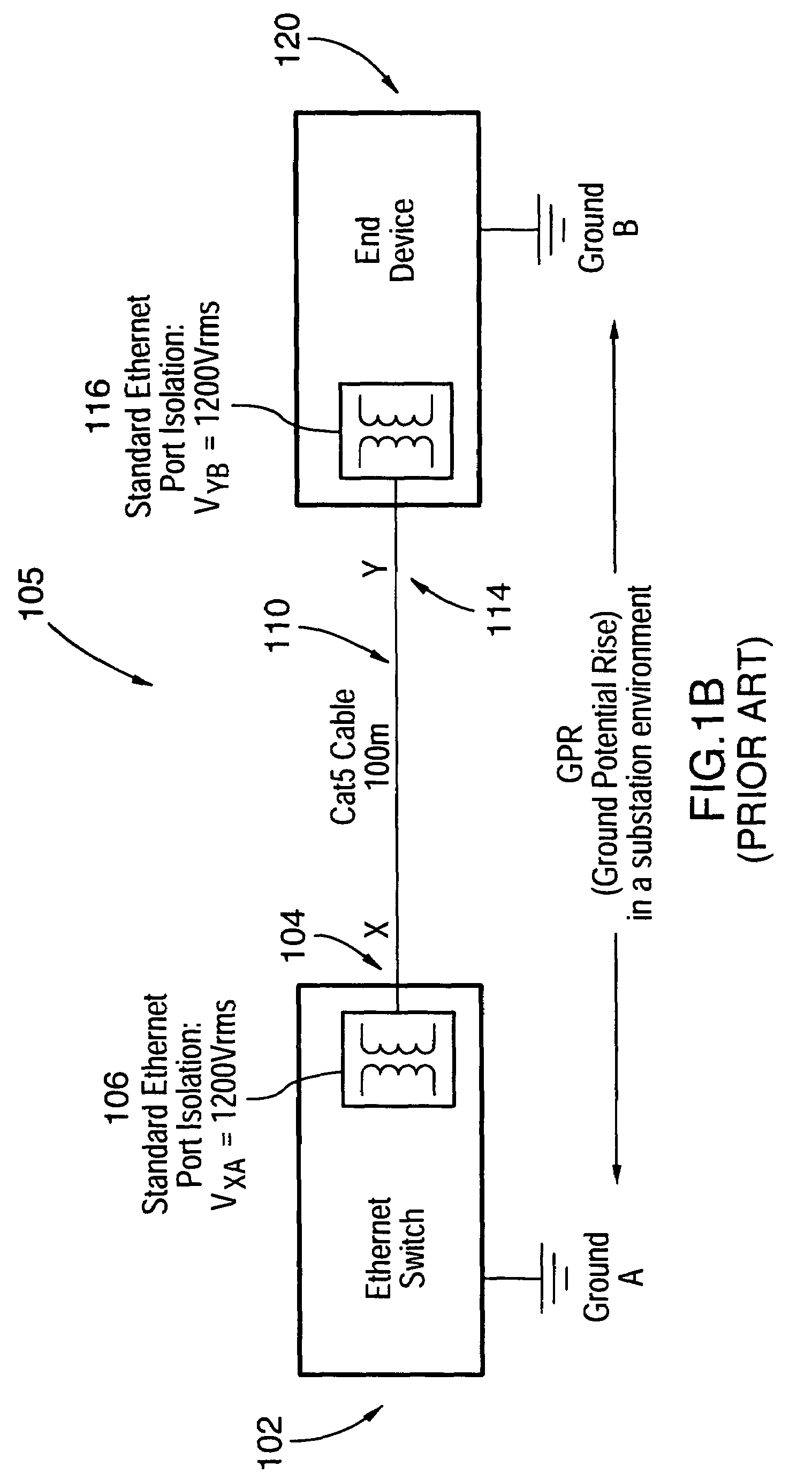
[0032]In a further aspect, the present invention provides a power supply circuit having increased immunity to ground potential rise (GPR) for Ethernet ports communicating via copper cable or indeed any type of electronic devices in a network which are separated by substantial distances such as more than 10 or 20 metres, and which have at least one electric connection between them. Such ground potential rises have been discussed above and illustrated in FIG. 1B and are decreased or at least can provide increased isolation of up to 6,000 VRMS between a ground potential rise at one electronic device in a network with respect to another IED in the network.
[0033]Communications equipment and electric utility substations should generally be capable of operating reliably in hot environments without the use of cooling fans. New standards such as IEEE 1613 recommend the following ranges:
[0037]Nevertheless, many manufacturers specify a range of −40 to +85° C. It is also crucial to note that safety approvals from regulatory bodies such as CSA or UL generally require input voltages above 72 V DC for the maximum power dissipation at the maximum rated temperature. For example, a power supply with a power output of 25 watts and an operating temperature of −40 to +85° C. would have to obtain CSA / UL 60950 safety approval at the maximum temperature of +85° C. when delivering the maximum output of 25 watts. This is one of the criteria which the power supply circuit of the present invention was intended to achieve.
[0038]A further advantage of the present invention is that, by having the electrical isolation, such as in the form of the first DC to DC converter and the second DC to DC converter, located between the external power source and the internal components, rather than between the ports with respect to each of the IEDs in the network, less isolation is required in the switch as a whole because clearly there will be more ports or electrical connections into an IED than power connections to ground. This decreases the overall cost of the system. Moreover, having electrical isolation in each port would greatly increase the heat generated by the IED.

Problems solved by technology

However, the prior art Ethernet switches and some other electronic devices do not meet these standards.
In particular, the switch is susceptible to electrical transients and electromagnetic interference being coupled into the device via twisted pair copper cables 8.
This is extremely undesirable since it could result in corruption of real-time mission critical control messages being transmitted over the network via the switch.
Moreover, actual damage to the switch itself is possible if high voltage electrical transients are directly coupled into the device via the copper cables overcoming the limited electrical isolation (typically 1000V to 1500V RMS) provided by isolation transformers 5b.
This is not a requirement for commercial grade Ethernet Switches and thus the power supply inputs 6a do not provide suitable transient suppression circuitry.
Furthermore, commercial grade Ethernet switches are not specifically designed to withstand EMI (Electromagnetic Interference) levels of 35V / m as specified by ANSI / IEEE C37.90.2 (1995) which is typical of many substation environments.
Accordingly, conventional circuit 10 suffers from the disadvantage that it is susceptible to electrical transients and electromagnetic interference at levels which are possible, or even common, in utility substation environment.
The design of FIG. 1A is also susceptible to mechanical breakdown because of the use of rotating cooling fan 7 required to cool the electronic components.
However, the operating temperature range for devices in the substation environment such as protective relays is specified by the IEC 60255-6 (1998) standard as −25° C. to +55° C. Therefore, not only is the circuit 10 of FIG. 1A susceptible to failure, it also does not meet the requirements of the environmental conditions which are possible, or even common, in utility substation environments.
One potential communication equipment fault which may arise, particularly in, but not exclusively in electric utility substations, includes a ground potential rise (GPR).
Because the Ethernet switches and other IEDs may be located in a network that covers a large area, a ground potential rise within one location may have catastrophic effects to the components in that area and / or the components in other areas.
For instance, any equipment with copper wire connections across the location of the ground potential rise, such as, for example, an Ethernet switching hub located in the control room connecting to a protective relay device or intelligent switch gear device in a switch yard, will experience high levels of ground potential rise which can damage the equipment by causing the galvanic isolation barriers between the two connected devices, such as the Ethernet switch in the control room and the protective relay in the switch yard, to break down.
In this way, the internal components of the electronics could be exposed to high voltages and currents causing potential physical damage.
For communication equipment interfacing using electrical connections such as by copper wire, or a combination of electrical connections and fibre optical media, and / or a single electrical connection using copper wire or other conductive material, any ground potential rise presents a serious concern.
It is also apparent that such damage could occur at a critical time, thereby damaging the overall network precisely when communication is most critical.

Method used


Image

  • Environmentally hardened ethernet switch
  • Environmentally hardened ethernet switch
  • Environmentally hardened ethernet switch

Examples


Embodiment Construction

[0056]A preferred embodiment of the present invention and its advantages can be understood by referring to the present drawings. In the present drawings, like numerals are used for like corresponding parts of the accompanying drawings.

[0057]FIG. 2 illustrates an electronic circuit block diagram shown generally by reference numeral 20, for an Ethernet switch according to one embodiment of the present invention. The circuit consists of an Ethernet Media Access Controller (MAC) block 21 with integrated packet and address memory which provides a plurality of communications ports each adhering to the RMII (Reduced Media Independent Interfaces) signaling specification as put forth by the version 1.2 of the RMII Consortium. Such a block 21 may be implemented using Marvell 88E6050 or a Galileo GT48350.

[0058]These RMII ports interface to a multi-port physical layer device 22, referred to as a PHY, which converts the RMII signals to differential transmit and receive signal pairs in accordance...


PUM


Abstract

A device for hardening an Ethernet switch is disclosed. The device provides cooling for the switch, and, suppresses electrical transients and electromagnetic interference, which could affect the power supply, and data transmission of the Ethernet switch. Using this device, the Ethernet switch can be used in harsh industrial environments, such as those present in power utility substations. The Ethernet switch may comprise a dual stage isolated power supply. The dual stage isolated power supply has a first DC to DC converter for converting received power from the received voltage to an intermediate voltage. The intermediate voltage is then further converted to a voltage which can be used by the Ethernet switch. Each of the DC to DC converters also provide galvanic isolation and also transient suppression and electromagnetic interference filtering to decrease adverse electrical effects which may be inherent in the power received from an external source. The first and second DC to DC converter provides a first level of galvanic isolation which is greater than the second level of galvanic isolation provided by the second DC to DC converter. The power supply circuit can be used in an Ethernet switch as well as any other intelligent electronic device.

Description

[0001]This is a continuation-in-part of U.S. application Ser. No. 10 / 962,745 filed Oct. 13, 2004 for an invention entitled Environmentally Hardened Ethernet Switch, which is a continuation of U.S. application Ser. No. 10 / 330,148 filed Dec. 30, 2002 now abandoned for an invention entitled Environmentally Hardened Ethernet SwitchFIELD OF THE INVENTION[0002]The present invention relates in general to the field of suppression of electrical interference of power supplies for electrical devices used in computer communication networks. More specifically, the present invention relates to a method and apparatus for suppressing transient electrical interference of electrical devices including Ethernet switching hubs (Ethernet Switch) suitable for use in harsh industrial environments such as those found in electric power utility substations.BACKGROUND OF THE INVENTION[0003]Trends in the electric power utility automation sector, specifically substation automation, have been driving towards comm...

Claims


Application Information

Patent Timeline
Patent Type & Authority Patents(United States)
IPC IPC(8): H02J1/00H02H9/00
CPCG06F1/182G06F1/20H02M3/335H05K9/0066H04L12/10H05K7/1092H02M2001/007H02M1/007
Inventor POZZUOLI, MARZIO PARIDEXIE, XIAOYU
Owner SIEMENS CANADA LTD
Why Eureka
Eureka Blog
Learn More