
Beam switching antenna system and method and apparatus for controlling the same

a beam switching antenna and beam pattern technology, applied in the direction of antennas, polarised antenna unit combinations, protective material radiating elements, etc., can solve the problems of power levels producing a variety of negative effects, non-directional beam patterns, and inability to adapt to a peripheral environment or use, so as to reduce power consumption, minimize radiation exerted on the human body, and minimize the effect of searching for the optimal beam-oriented direction

Active Publication Date: 2007-09-25
LG UPLUS
View PDF15 Cites 24 Cited by
  • Summary
  • Abstract
  • Description
  • Claims
  • Application Information

AI Technical Summary

Benefits of technology

[0013]It is another object of the present invention to provide a method of controlling a beam switching antenna system and apparatus thereof, by which electromagnetic waves of a beam generated from an antenna are controlled to minimize the radiation exerted on a human body.
[0014]It is another object of the present invention to provide a method of controlling a beam switching antenna system and apparatus thereof, by which the necessary time for searching an optimal beam-oriented direction is minimized as well as power consumption thereof is reduced.

Problems solved by technology

An inherent characteristic of the above omni-directional antenna is that its beam pattern is non-directional and thus cannot be adapted to a peripheral environment or usage condition, which may call for a directional beam pattern.
Reverse-link transmission at greater power levels produces a variety of negative effects, including reduced data through rates, increased error rates, and a lowered forward-link communication capacity per cell.
Accordingly, the use of an omni-directional antenna in such cases inherently causes raised concerns.
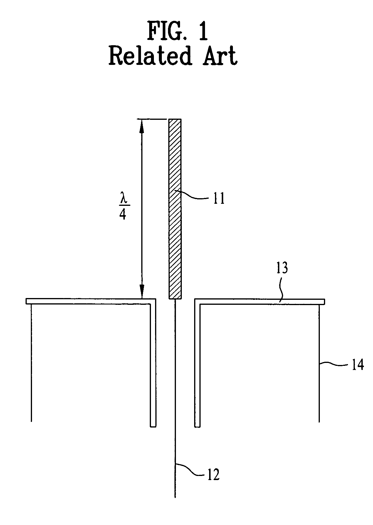
Moreover, the length of the antenna adopted by a mobile communication terminal, such as a cellular telephone, is desirably short to facilitate miniaturization while maintaining an aesthetically pleasing exterior, and the operating band of the mobile communication terminal is fixed such that the λ / 4 length of the omni-directional antenna cannot be shortened.
As such, the adaptive directional antenna is too large, too costly, and too slow and is thus impractical for a mobile communication terminal.
The reverse link power must be boosted throughout the search operation for determining the optimal beam direction, which increases power consumption and produces the same negative effects of an omni-directional antenna.

Method used


Image

  • Beam switching antenna system and method and apparatus for controlling the same
  • Beam switching antenna system and method and apparatus for controlling the same
  • Beam switching antenna system and method and apparatus for controlling the same

Examples


first embodiment

[0053]Referring to FIG. 8, an apparatus for controlling the ground switches of a beam switching antenna system according to the present invention comprises an earphone sensing circuit 51, a mode signal generating circuit 52, a base station signal receiving circuit 53, and a controller 9 which includes the above-described control circuit for generating the control signal for selectively operating the ground switches. When an earphone is connected to a mobile communication terminal, the earphone sensing circuit 51 senses the connection and generates earphone sensing data Ep. The mode signal generating circuit 52 senses the terminal's mode of operation, i.e., whether the mobile communication terminal operates in a traffic mode through a traffic channel established between an originator and a recipient or in an idle mode where the traffic channel is cut off, and then generates traffic / idle mode data Tr / Id indicating the terminal's current mode. The beam formation of the antenna system i...

second embodiment

[0059]FIG. 11 illustrates a method of controlling a beam switching antenna system according to another embodiment of the present invention, using the apparatus of FIG. 8, which is explained together with FIGS. 12A-12C in which first and second base stations 71 and 72 are shown.

[0060]Referring to FIG. 11, an initialization procedure is executed in a step S91, for receiving base station signals RB transmitted from the base stations 71 and 72 on a forward link via the beam switching antenna system 91 installed at the mobile communication terminal 90 and for synchronizing the mobile communication terminal and base stations. The controller 9 then controls in a step S92 the ground switches 5a-5d in an omni-directional mode to form a non-directional beam 60 as shown in FIG. 12A. In doing so, the beam switching antenna system 91 of the mobile communication terminal 90 receives all signals transmitted from the first and second base stations 71 and 72. After receiving the base station signals...


PUM


Abstract

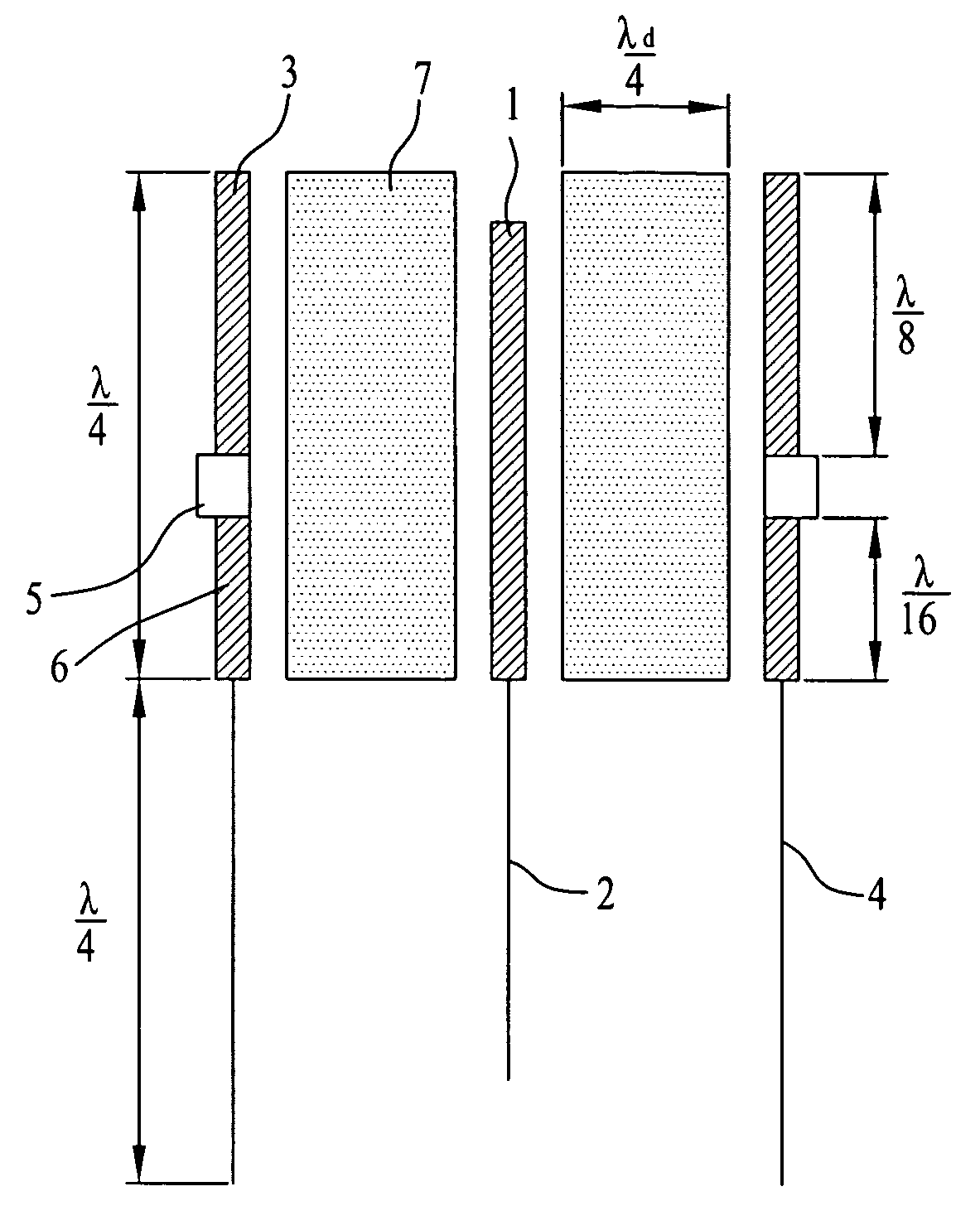
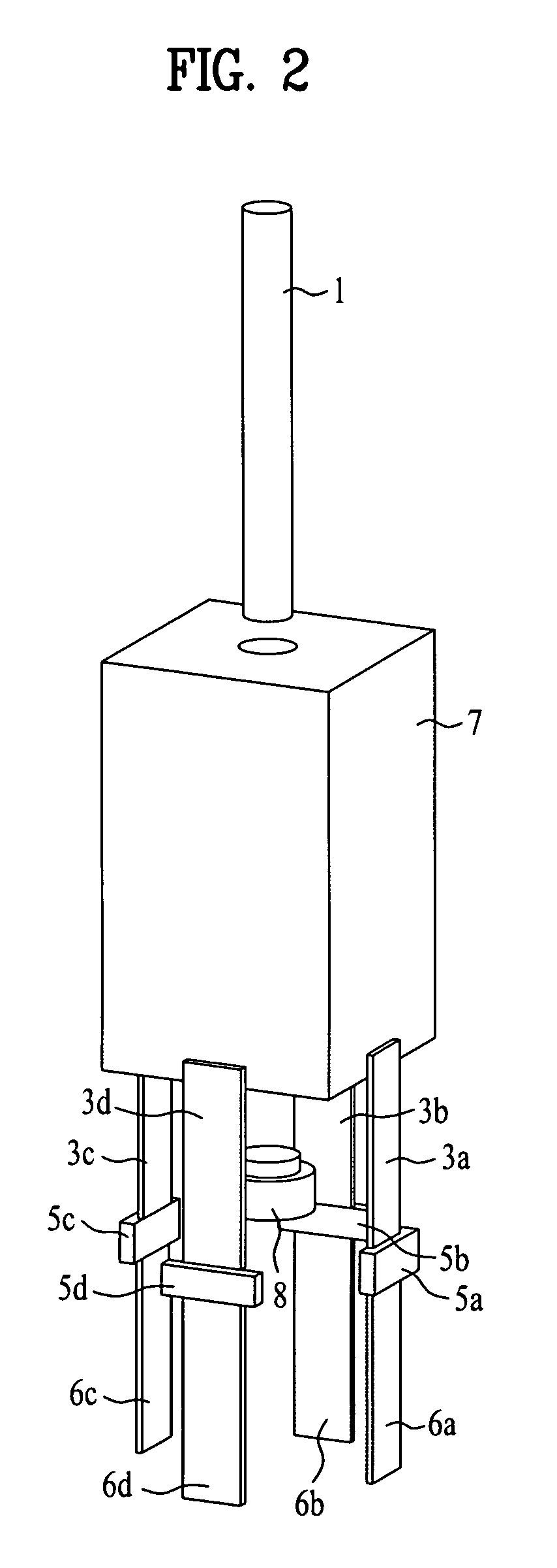
A beam switching antenna system and method and apparatus for controlling the same is provided, by which optimal antenna characteristics can be maintained according to a peripheral environment, the necessary time and power consumption of searching an optimal beam-direction can be reduced, and electromagnetic waves of a beam generated from an antenna can be minimized. The beam switching antenna system includes an antenna element for transmitting and receiving a beam; a dielectric body surrounding said antenna element; at least one conductive reflector facing a lateral outside of said dielectric body; and a ground switch circuit connected to said at least one conductive reflector. The ground switch circuit includes a reference voltage source generating a reference voltage; a ground line connected to the reference voltage source; an electrical switching device connected between the ground line and the conductive reflector; and a controller for controlling the electrical switching device. The conductive reflector includes an upper conductive reflector having one end connected to one terminal of the electrical switching device; and a lower conductive reflector having one end connected to another terminal of the electrical switching device and the other end connected to the ground line.

Description

[0001]This application claims the benefit of Korean Applications No. 10-2003-0063788 filed on Sep. 15, 2003, No. 10-2003-0065305 filed on Sep. 19, 2003, and No. 10-2003-0065306 filed on Sep. 19, 2003, which are hereby incorporated by reference.BACKGROUND OF THE INVENTION[0002]1. Field of the Invention[0003]The present invention relates to beam switching antennae, and more particularly, to a beam switching antenna system and a method and apparatus for controlling the same, by which optimal antenna characteristics can be maintained according to a peripheral environment, the necessary time and power consumption of searching an optimal beam-direction can be reduced, and electromagnetic waves of a beam emanating from an antenna toward the user's head can be minimized.[0004]2. Discussion of the Related Art[0005]Antenna configurations include a Yagi-type, parabolic, helical, planar, and the like, with beam patterns which may be classified as directional or omni-directional. A contemporary ...

Claims


Application Information

Patent Timeline
Patent Type & Authority Patents(United States)
IPC IPC(8): H01Q3/02H01Q19/10H01Q1/24H01Q1/40H01Q3/00H01Q3/24H01Q3/44H01Q15/14H01Q19/09H01Q19/26H01Q19/30H01Q21/26H04B1/38H04B1/3822
CPCH01Q1/40H01Q3/24H01Q3/44H01Q19/10H01Q19/30H01Q19/32H01Q25/00
Inventor LEE, HYO JIN
Owner LG UPLUS
Learn More