
Optical fiber filter for suppression of amplified spontaneous emission

an optical fiber filter and amplified spontaneous technology, applied in the field of allfiber optical filters, can solve the problems of affecting system performance, not sufficiently reducing other system impairments, and problematic reflection gratings, and achieve the effect of reducing amplified spontaneous emission

Active Publication Date: 2007-09-18
FURAKAWA ELECTRIC NORTH AMERICA INC
View PDF26 Cites 43 Cited by
  • Summary
  • Abstract
  • Description
  • Claims
  • Application Information

AI Technical Summary

Benefits of technology

The solution effectively reduces ASE and noise power, enhancing amplifier performance by increasing loss at noise wavelengths while maintaining low loss at desired signal wavelengths, with a high extinction ratio and improved power efficiency.

Problems solved by technology

Optical fiber systems are known to be sensitive to a variety of different sources of “optical noise” (extraneous signals at wavelengths other than the desired wavelength(s)) that result in impairing the system performance.
While such discrete filters may be able to reduce the accumulated noise power, they may not sufficiently reduce other system impairments, such as power lost due to noise amplification.
While various in-line arrangements have been successful in providing some filtering, reflection gratings are problematic for in-line filtering in amplifiers, since reflections can lead to unwanted oscillations or lasing at the noise wavelengths.
While some distributed filter embodiments can provide effective filtering, this method requires additional processing steps in fiber fabrication, and restricts the dopant profile of the fiber to those with appropriate photosensitivity.

Method used


Image

  • Optical fiber filter for suppression of amplified spontaneous emission
  • Optical fiber filter for suppression of amplified spontaneous emission
  • Optical fiber filter for suppression of amplified spontaneous emission

Examples


Embodiment Construction

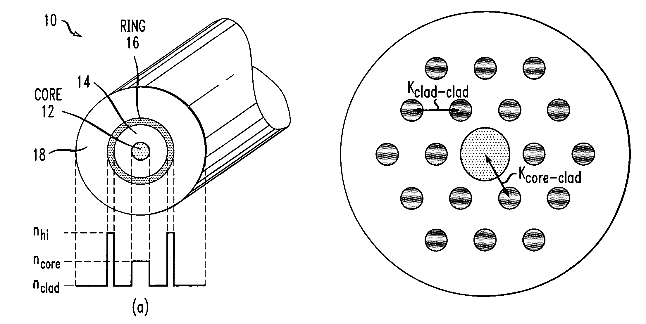
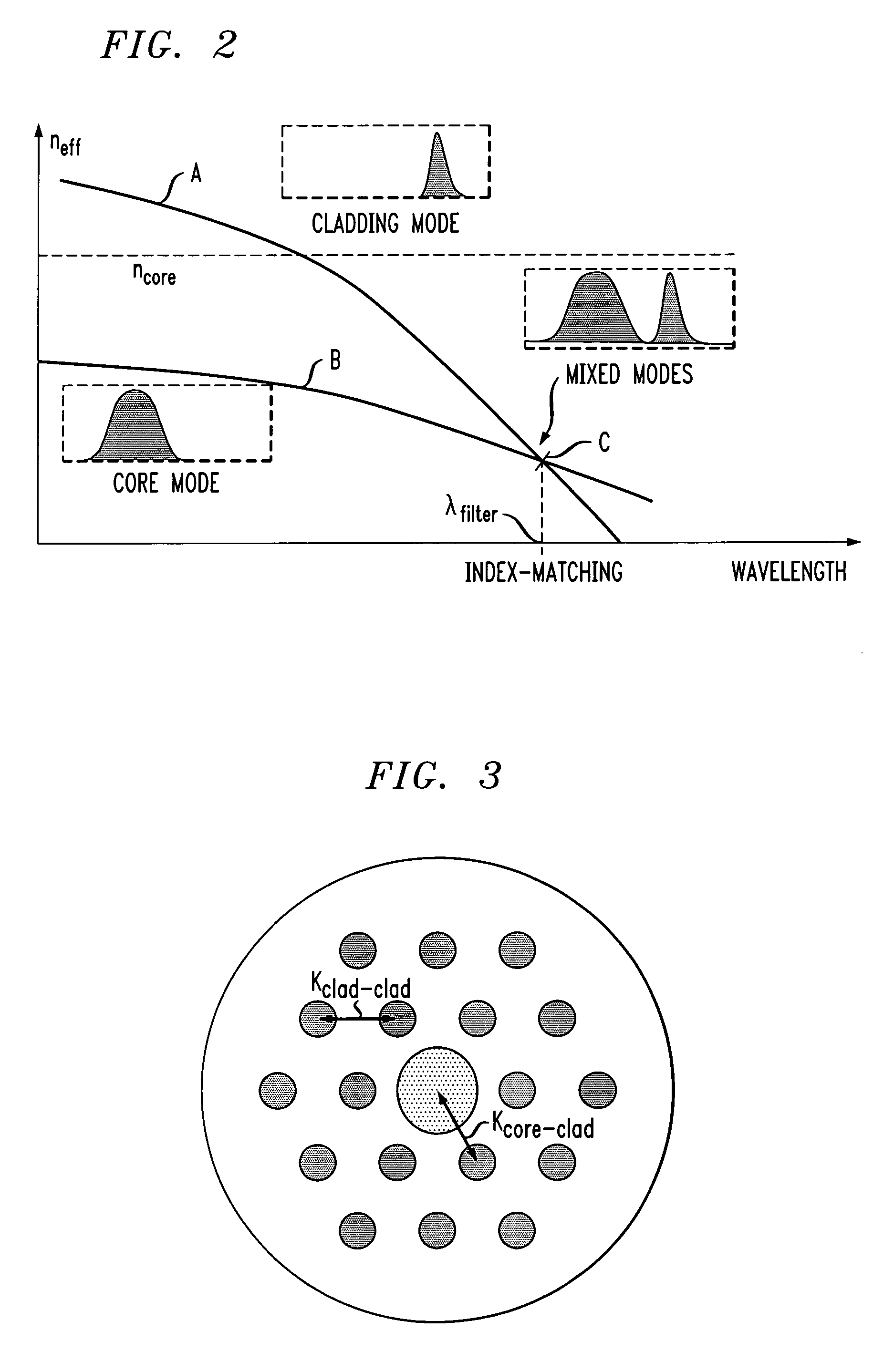
[0018]As mentioned above, there are a variety of different optical systems that can be improved, in terms of performance, by the application of wavelength-selective filtering to the signals propagating along the system optical fiber. In particular, “optical noise” can be reduced by selectively removing signals at certain wavelengths from propagating along the fiber. In accordance with the present invention, an all-fiber optical filter has been developed that exhibits separate cladding modes and core modes in the pass band(s) of interest, but exhibits only mixed core-cladding modes in the stop band(s). Mode mixing leads to reduced overall transmission via reduced gain and / or increased losses within the core region as a result of the signal coupling into the cladding region. An all-fiber filter formed in accordance with the present invention is based upon the following design principles: (1) a raised-index core region that guides light (propagating at desired wavelength(s)) primarily ...


PUM


Abstract

An in-line, distributed optical fiber filter comprises a core region with a raised refractive index (with respect to the surrounding cladding material) so as to allow for total internal reflection (TIR) of the desired transmission wavelength(s). One or more raised index features are formed within the cladding region and are configured so as to result in mode mixing between the cladding mode and core mode at determined wavelength(s) to be removed by filtering. The parameters associated with determining the proper core specifications and cladding specifications can be separately determined to provide for enhanced performance in terms of both filtering unwanted signals and propagation of desired communication signals.

Description

TECHNICAL FIELD[0001]The present invention relates to an all-fiber optical filter and, more particularly, to an all-fiber optical filter comprising selective arrangements of core and cladding material to provide for wavelength-selective filtering, helpful in reducing amplified spontaneous emission (ASE).BACKGROUND OF THE INVENTION[0002]Optical fiber systems are known to be sensitive to a variety of different sources of “optical noise” (extraneous signals at wavelengths other than the desired wavelength(s)) that result in impairing the system performance. Various types of filtering arrangements have been proposed through the years to address this problem. Discrete filtering elements (incorporating multiple thin film layers) have been used to remove selected wavelengths from propagating along the fiber. While such discrete filters may be able to reduce the accumulated noise power, they may not sufficiently reduce other system impairments, such as power lost due to noise amplification....

Claims


Application Information

Patent Timeline
Patent Type & Authority Patents(United States)
IPC IPC(8): G02B6/02G02B6/032G02B6/293
CPCG02B6/0238G02B6/03611G02B6/03644G02B6/03688G02B6/29332G02B6/02042G02B6/02347G02B6/02366G02B6/105
Inventor BISE, RYAN TYLERFINI, JOHN MICHAELYAN, MAN FEI
Owner FURAKAWA ELECTRIC NORTH AMERICA INC
Learn More