Method and apparatus for providing mobility within a network

Inactive Publication Date: 2007-09-18
QUALCOMM INC
View PDF12 Cites 7 Cited by
  • Summary
  • Abstract
  • Description
  • Claims
  • Application Information

AI Technical Summary

Benefits of technology

[0012]All embodiments of the present invention are novel methods and apparatus for handling mobility within a serving network of a wireless telecommunications system. The exemplary embodiment of the present invention has broader applicability, in that it provides a novel method for handling mobility in all types of networks, including corporate and government networks. Other mobility models can require a centralized network to manage anchor point mobility. Additionally, other mobility models can use of a significant amount of available bandwidth and can significantly increase latency. The present invention neither has deleterious latency nor bandwidth effects. Additionally, the present invention utilizes standard protocols that are widely available from a plurality of equipment manufacturers on a variety of platforms. Thus, the present invention provides a very cost-effective model for network providers that desire to support transparent mobility within their network.
[0013]The exemplary embodiment of the present invention uses OSPF to achieve transparent anchor point mobility. Mobile IP is used in an alternative embodiment of the present invention to provide transparent anchor point mobility in the serving network of a wireless telecommunications system. OSPF is used in the exemplary embodiment of the present invention because the use of OSPF does not introduce the tunneling overhead that is introduced in Mobile IP, and OSPF does not introduce the latency that can be caused by the indirect routing common in Mobile IP.

Problems solved by technology

Additionally, other mobility models can use of a significant amount of available bandwidth and can significantly increase latency.

Method used


Image

  • Method and apparatus for providing mobility within a network
  • Method and apparatus for providing mobility within a network
  • Method and apparatus for providing mobility within a network

Examples


Embodiment Construction

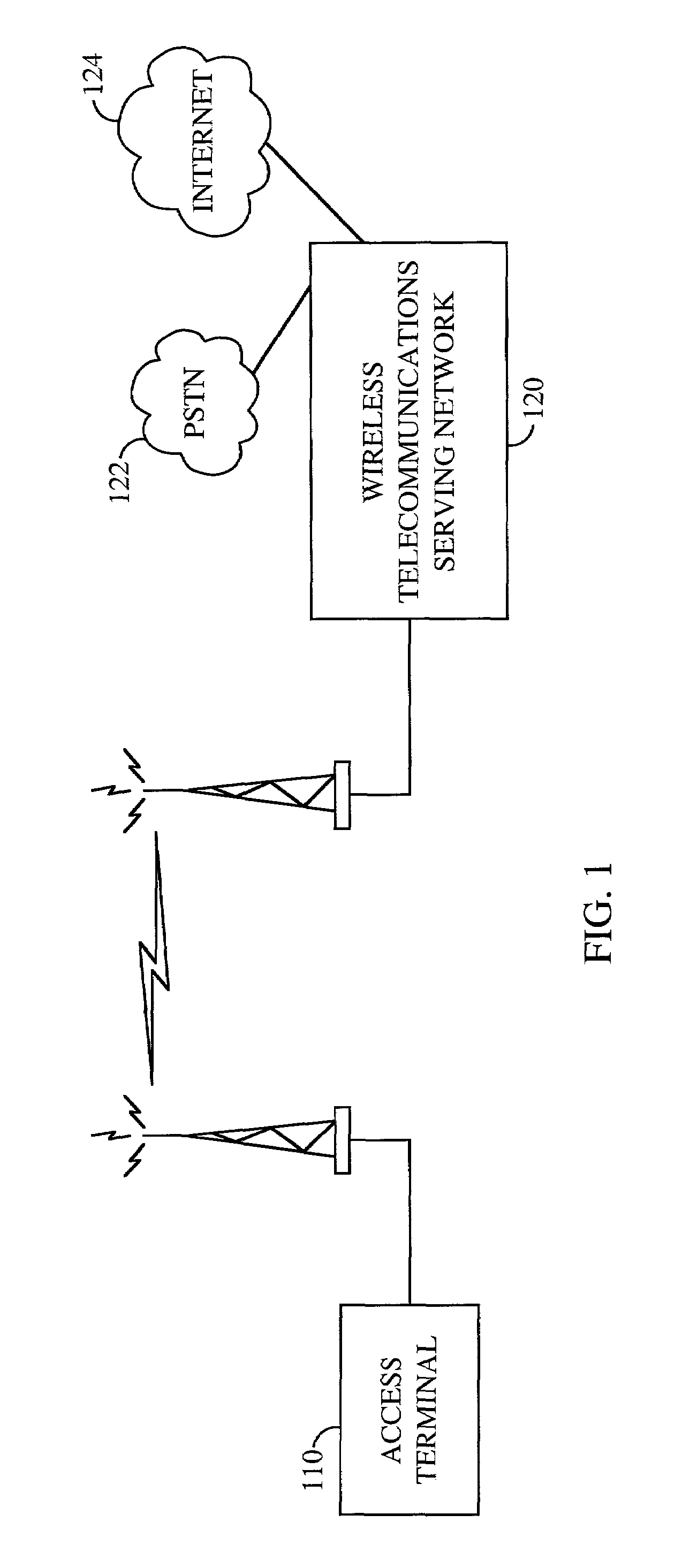
[0030]FIG. 1 is a block diagram of exemplary embodiment of an Access Terminal in communications with a Wireless Telecommunications Decentralized Serving Network. Access terminal 110 is a wireless terminal that can be used to access one or more of a plurality of services, including Public Switched Telephone Network (PSTN) and Internet services, offered by the serving network of a wireless telecommunications system 120. Wireless telecommunications system 120, and PSTN 122 and Internet 124 to which wireless telecommunications system 120 connects, are further described in reference to FIG. 2. In the exemplary embodiment, access terminal 110 is able to connect to the serving network of a wireless telecommunications system via the use of a radio antenna. Access terminal 110 can maintain a communication link with the serving network of a wireless telecommunications system by communicating with one or more access points, further described in reference to FIG. 2 and FIG. 3.

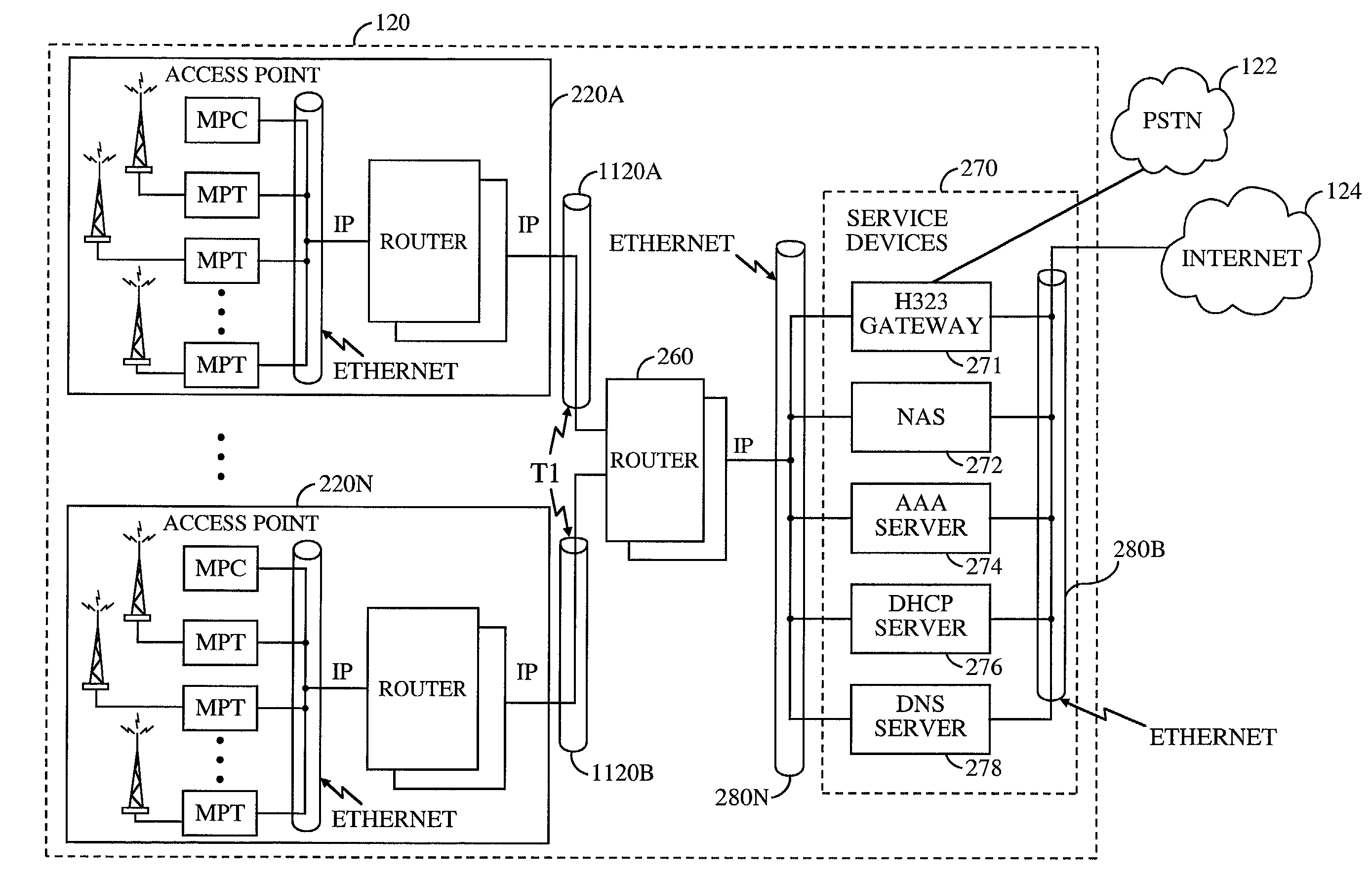
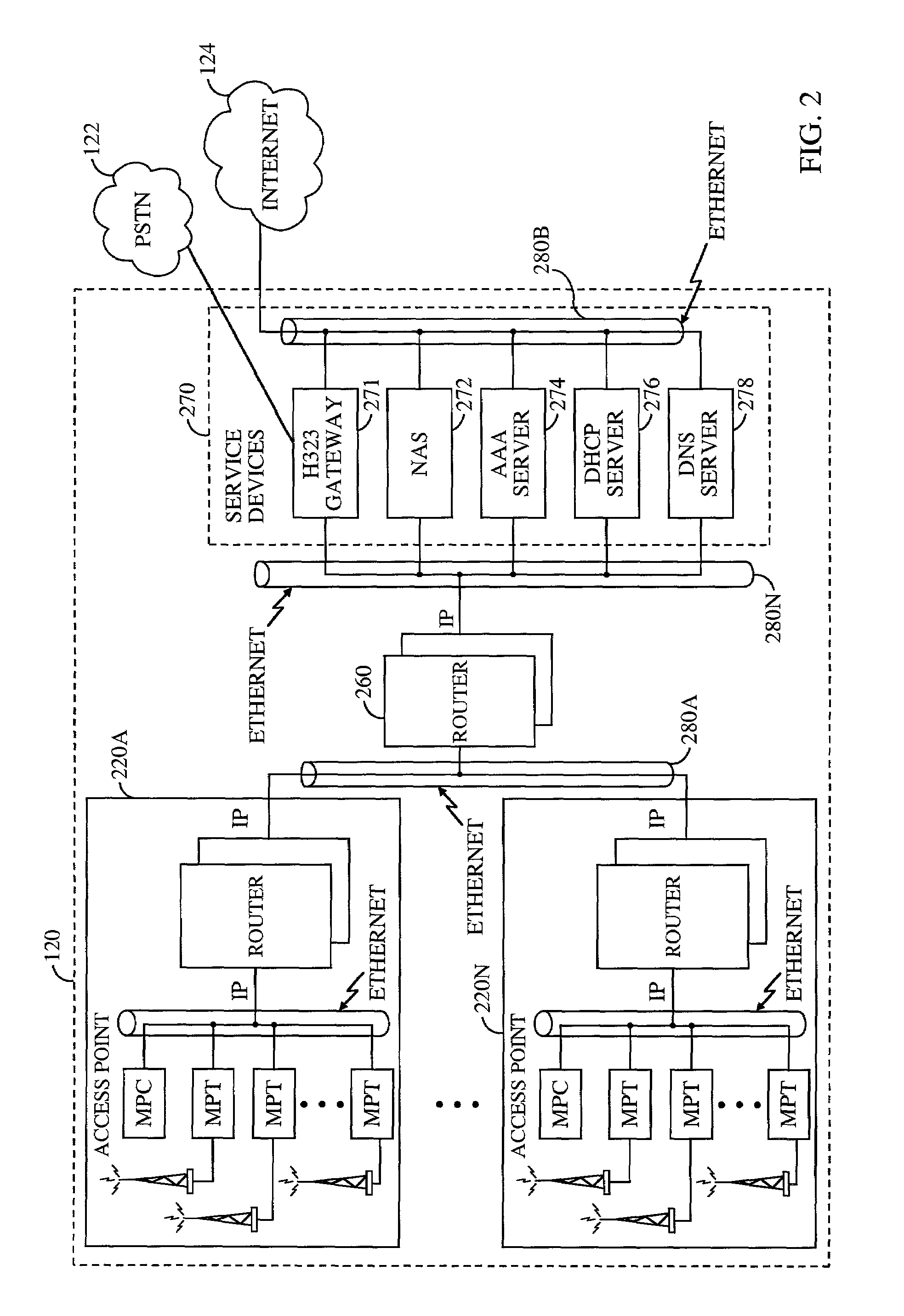
[0031]FIG. 2 is a ...


PUM


Abstract

A novel method and apparatus is presented for providing transparent mobility of an entity within a network, by allowing the entity, which has a communication path set up between it and a peer entity, to move from one location to another, without informing the peer entity of this movement, and without having the communication path broken. The invention is applicable to decentralized networks using IP protocols, and is particularly applicable on networks where the mobility mechanism neither introduces latency nor decreases the available bandwidth of the network. In the invention, neither is latency increased nor is bandwidth utilization increased, as is done in other mobility models. Additionally, the invention utilizes standard protocols that are widely available from a plurality of equipment manufacturers on a variety of platforms. Thus, the invention provides a very cost-effective model for network providers that need to support transparent mobility within their networks.

Description

CROSS REFERENCE OF APPLICATION[0001]This application claims priority from U.S. application Ser. No. 09 / 451,400, filed Nov. 30, 1999, entitled “Method and Apparatus for Providing Mobility Within a Network” which claims priority from Provisional Application Ser. No. 60 / 163,325, filed Nov. 3, 1999, both currently assigned to the assignee of the present application.BACKGROUND OF THE INVENTION[0002]I. Field of the Invention[0003]The current invention relates to mobility within a telecommunications system. More particularly, the present invention relates to a method and apparatus for transparently relocating an anchor point within the serving network of a wireless telecommunications system from one location to another.[0004]II. Description of the Related Art[0005]The use of a decentralized serving network for use in a wireless telecommunications system is disclosed in U.S. Pat. No. 6,215,779, entitled “DISTRIBUTED INFRASTRUCTURE FOR WIRELESS DATA COMMUNICATIONS”, applied for by the applic...

Claims


Application Information

Patent Timeline
IPC IPC(8): H04L12/56H04L29/06H04W12/10H04W36/00H04W36/12H04W40/02H04W80/04
CPCH04W36/14H04W80/04H04W40/02H04W36/1446H04W8/26H04W88/08
Inventor BENDER, PAUL E.
Owner QUALCOMM INC
Why Eureka
Try Eureka