Stepping motor for generating vibration
a stepping motor and vibration technology, applied in the direction of mechanical energy handling, electrical apparatus, dynamo-electric machines, etc., can solve the problems of deteriorating ratio of input to output of the motor, difficulty in reducing the thickness of the device, and disconnection of eccentric disks, so as to enhance the efficiency of utilizing the magnetic flux, increase imbalance, and enhance the effect of mobility
- Summary
- Abstract
- Description
- Claims
- Application Information
AI Technical Summary
Benefits of technology
Problems solved by technology
Method used
Image
Examples
embodiment 1
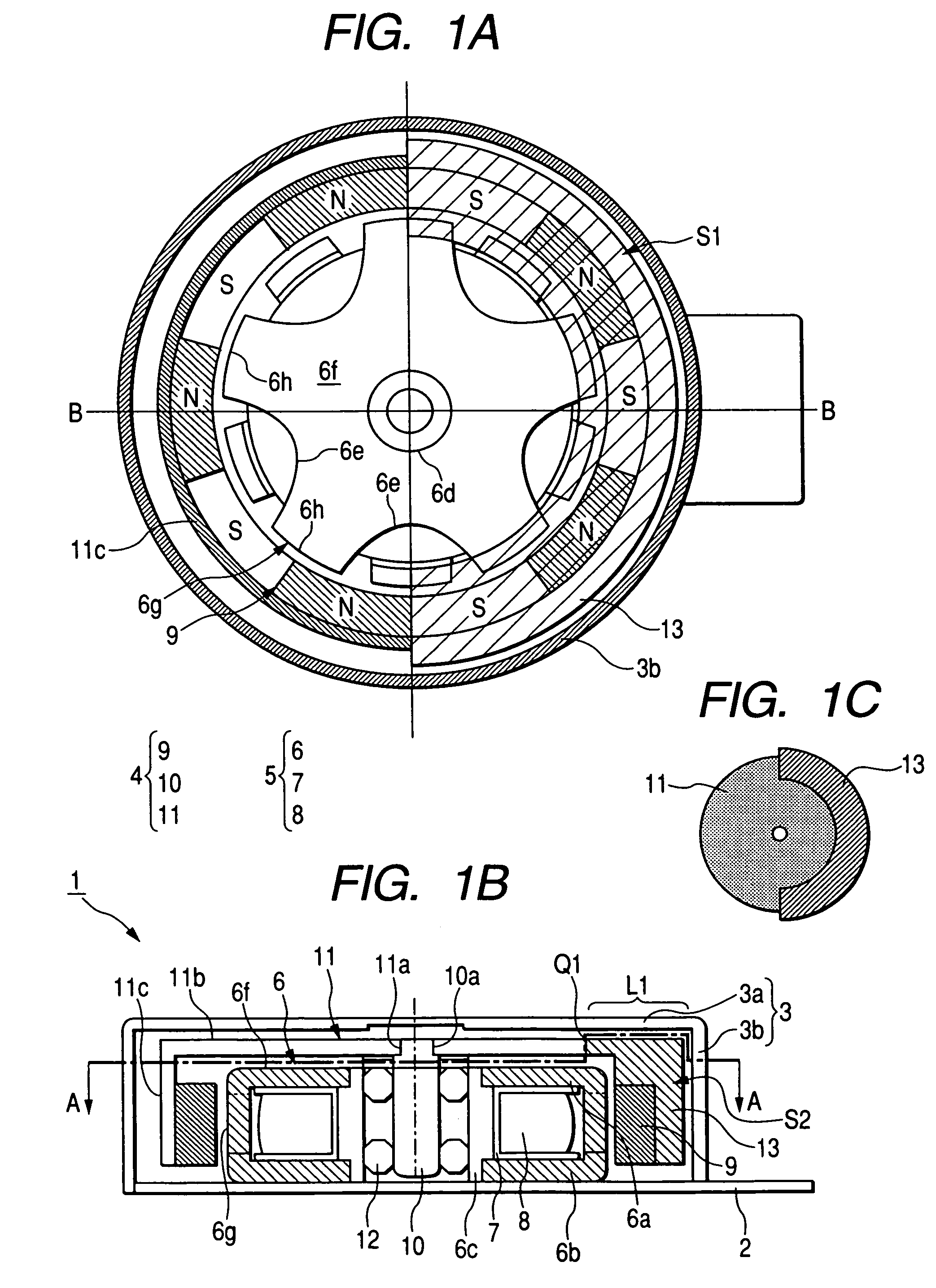
[0088]FIGS. 1A to 1C are arrangement views of an exemplary embodiment of an outer rotor type stepping motor for generating vibration which is a basic stepping motor for generating vibration of the invention. FIG. 1A is a sectional view taken on line A-A in FIG. 1B, FIG. 1B is a sectional view taken on line B-B in FIG. 1A, and FIG. 1C is a plan view of a rotor frame. An outer rotor type stepping motor 1 for generating vibration includes an interface base board 2, cover 3, rotor 4 and stator 5.
[0089]In the interface board 2, an insulating film is provided on a metallic plate, necessary wiring such as a feeder connected to a coil is provided on the insulating film, and an opening (not shown) engaged with a protrusion (not shown) of the cover 3 is formed. A second stator yoke 6b on the interface board 2 side of a stator yoke 6 and a center yoke 6c, which becomes a third stator yoke, are fixed onto the interface board 2. A protrusion (not shown) on the end face of a cylindrical portion 3...
embodiment 2
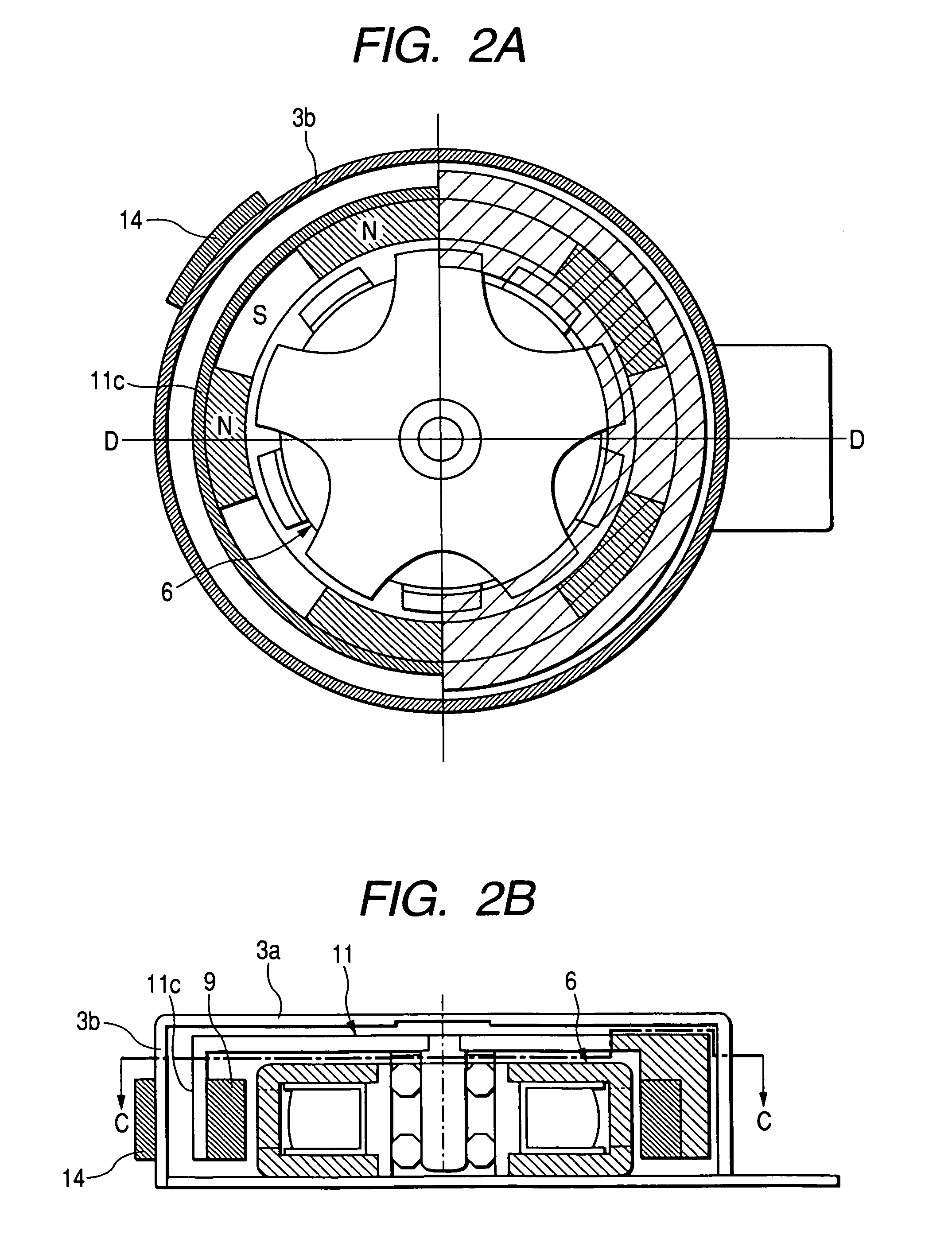
[0136]FIGS. 2A and 2B are arrangement views showing a starting position-adjusting means (1) of the invention. FIG. 2A is a sectional view taken on line C-C in FIG. 2B, and FIG. 2B is a sectional view taken on line D-D in FIG. 2A.
[0137]Like reference characters are used to indicate like parts in Embodiments 1 and 2, and the same explanations are omitted here. An arcuate length of a auxiliary pole magnet 14 is smaller than the pole teeth pitch of the stator yoke 6. The auxiliary pole magnet 14 is magnetized to be N-pole and S-pole in the radial direction. The auxiliary pole magnet 14 has a function of shifting a stopping position of the rotor 4 after the exciting current of the stator coil 8 has been turned off. The auxiliary pole magnet 14 can be arranged at an arbitrary position on the cover 3 as long as the predetermined function can be exhibited by the auxiliary pole magnet 14 at the position.
[0138]Explanations will be made into the operation by which the rotor 4 is moved from the...
embodiment 3
[0144]FIGS. 3A and 3B are arrangement views showing a starting position-adjusting means (2) of the invention. FIG. 3A is a sectional view taken on line E-E in FIG. 3B, and FIG. 3A is a sectional view taken on line F-F in FIG. 3B.
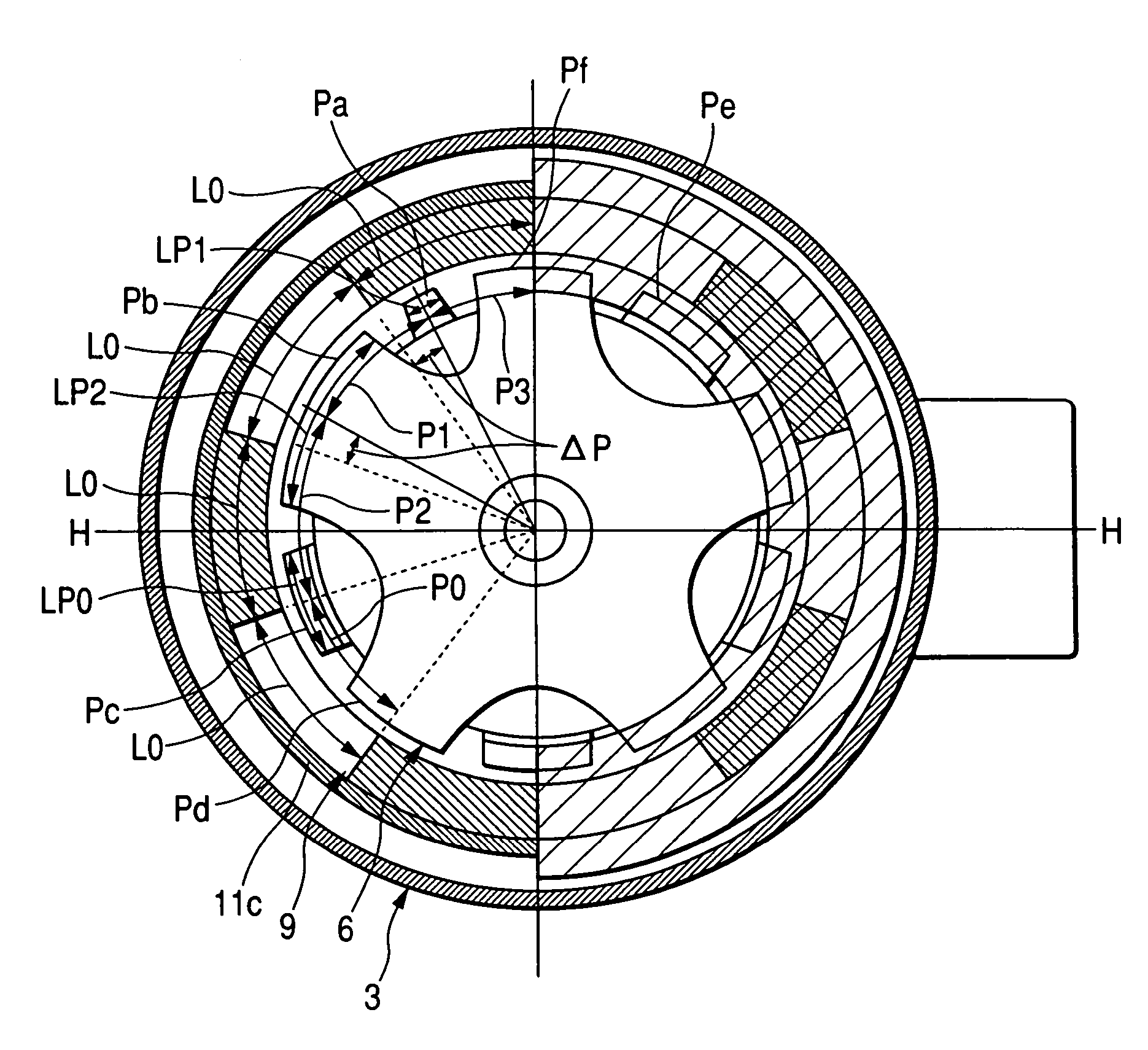
[0145]Like reference characters are used to indicate like parts in Embodiments 1 and 2, and the same explanations are omitted here. Magnetic pole pitches L1, L2 of N-pole and S-pole in at least one pair of magnetic poles of the ring magnet 9 are made to be not uniform compared with a magnetic pole pitch L0 of the other pair of the magnetic poles.
[0146]In this case, the ring magnet 9 includes one annular magnet formed by the multi-pole magnetization. Alternatively, the ring magnet 9 includes ten pairs of magnets, which are magnetized to be NS or SN in the radial direction from the axial center and are arranged and integrated into a ring shape so that the magnets can be alternately different magnetic poles along the inner circumferential face.
[0147]In FIG. 3A,...
PUM
 Abstract
Description
Claims
Application Information
 - R&D
- Intellectual Property
- Life Sciences
- Materials
- Tech Scout
- Unparalleled Data Quality
- Higher Quality Content
- 60% Fewer Hallucinations
Browse by: Latest US Patents, China's latest patents, Technical Efficacy Thesaurus, Application Domain, Technology Topic, Popular Technical Reports.
© 2025 PatSnap. All rights reserved.Legal|Privacy policy|Modern Slavery Act Transparency Statement|Sitemap|About US| Contact US: help@patsnap.com


