
Electrostatic precipitator for diesel blow-by

a technology of electrostatic precipitator and diesel engine, which is applied in the direction of magnetic separation, electrical supply techniques, chemistry apparatus and processes, etc., can solve the problems of electromagnetic waves, high-temperature, and high-pressure gas that can leak past the piston rings of the diesel engine to the crankcase, so as to reduce the high frequency emissions, eliminate gaps or crevices, and minimize electromagnetic interferen

Inactive Publication Date: 2007-09-11
MSP
View PDF36 Cites 12 Cited by
  • Summary
  • Abstract
  • Description
  • Claims
  • Application Information

AI Technical Summary

Benefits of technology

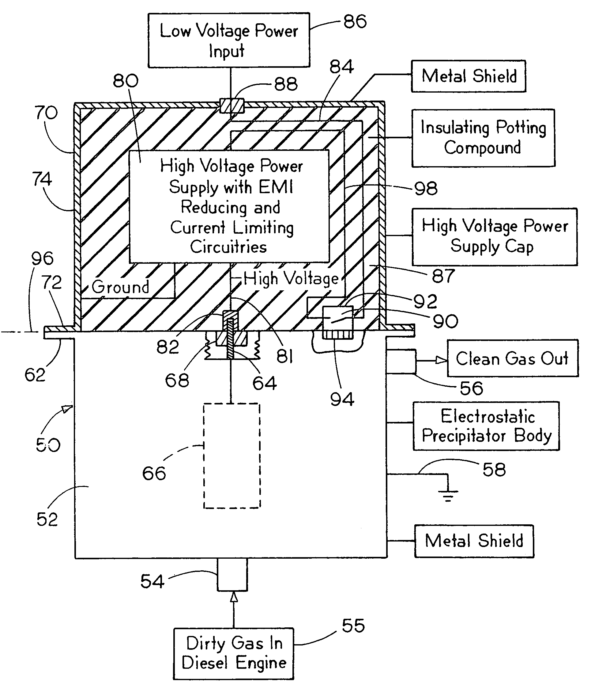
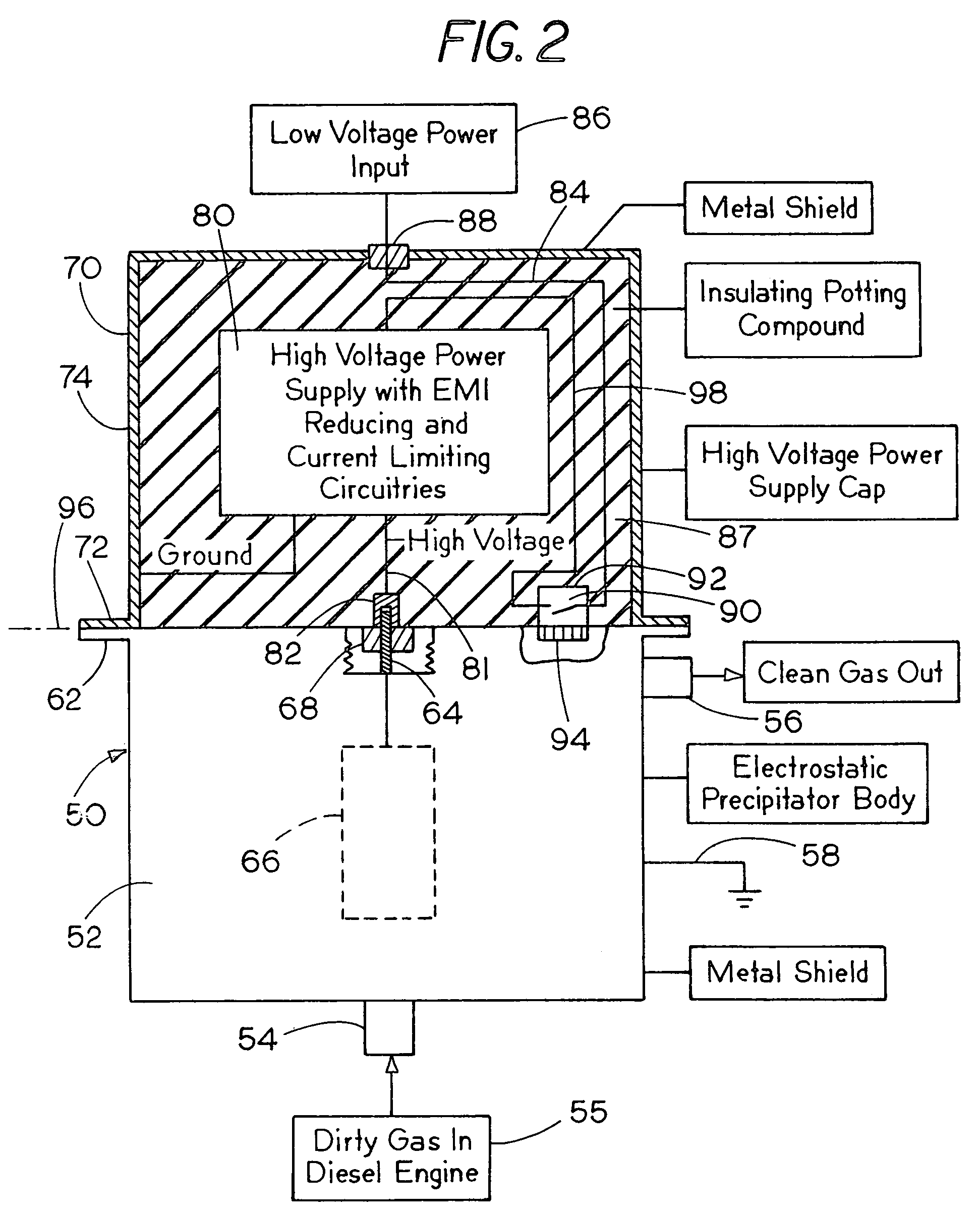
"The present invention is about an electrostatic precipitator construction that uses a separate high voltage DC power supply. This power supply can be easily assembled onto the precipitator housing to form a complete unit. The power supply is designed to provide the necessary DC voltage to the precipitator electrode, but the connection and mounting of the power supply housing disconnects the high voltage source from the electrode if the power supply housing is removed from the precipitator or electrode housing. The high voltage source is again connected to the electrode when the power supply housing is installed on the electrode housing. The invention also minimizes problems with electromagnetic interference and current limiting circuits or components are provided to control and limit the current if arcing occurs."

Problems solved by technology

Some of this high-temperature, high-pressure gas can leak past the piston rings of the Diesel engine to the crankcase.
However, in the presence of oil drops in the blowby gas from a Diesel engine, a thin film of oil is formed on the collecting surface.
The high voltage DC power source may also cause arcing and the emission of electromagnetic waves that can interfere with the engine control computer and other sensitive electronic circuitry nearby.

Method used


Image

  • Electrostatic precipitator for diesel blow-by
  • Electrostatic precipitator for diesel blow-by
  • Electrostatic precipitator for diesel blow-by

Examples


Embodiment Construction

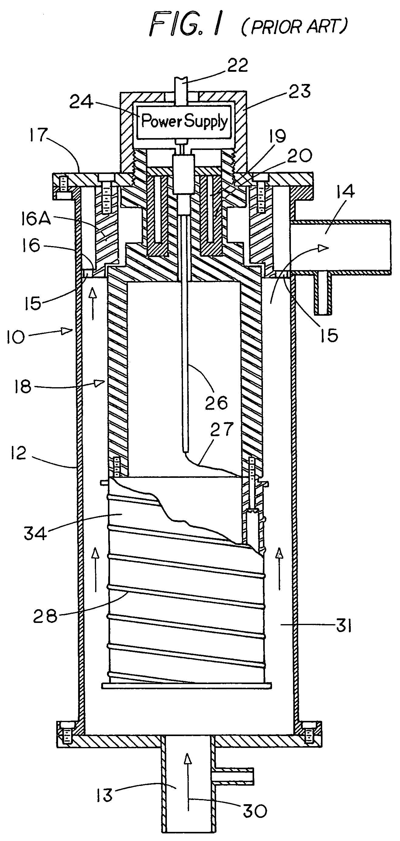
[0021]FIG. 1 is a vertical cross-sectional view of a prior art compact electrostatic precipitator 10. A conductive sleeve or housing 12 forms a passage for fluid, with an inlet connection 13 for receiving an aerosol, and an outlet connection 14. Conductive sleeve 12 is also a collector electrode. A flow passageway is defined by a plurality of openings 15 in a housing plate 16 that is supported on a sleeve 16A, which is positioned at the upper end of the conductive sleeve 12, and is supported on a cap plate 17.

[0022]An insulated main electrode support 18 is supported on the cap plate 17 in a suitable manner with an insulator block that includes cartridge heaters 19. The cartridge heaters are mounted in a heat conducting jacket 20. The jacket 20 distributes the heat uniformly to its outer surface and keeps the insulator support surface hot and clean to avoid contamination by vapor condensation and particle deposition.

[0023]A power connection line 22 can be passed out through a central...


PUM


Abstract

A compact electrostatic precipitator is designed specifically for use in connection with eliminating particles from crankcase emissions of a Diesel engine. Such emissions may carry solid soot particles as well as suspended oil droplets. The electrostatic precipitator has an electrode housing in which a high voltage electrode is mounted, and the emissions from the crankcase of a Diesel engine are passed across the electrode to an outlet. A high voltage power supply is mounted in a separate housing, and the output of the high voltage power supply is connected to the electrode only when the electrode housing and the power supply housing are properly mated, to thereby disable the high voltage connection to the electrode when the power supply housing is removed. A current limiting device is used in the circuit to the power supply to prevent high currents from being carried if any arcing occurs, and a normally open switch is closed to provide input power to the high voltage circuitry only when the power supply housing and the electrode housing are mated.

Description

[0001]This application claims priority on U.S. Provisional Application Ser. No. 60 / 505,176 filed Sep. 23, 2003, and the contents of which Provisional Application Ser. No. 60 / 505,176 are incorporated by reference.[0002]The present invention relates to improvements over the disclosure of U.S. Pat. No. 6,221,136, which issued Apr. 24, 2001, the contents of which is incorporated by reference.BACKGROUND OF THE INVENTION[0003]The present invention relates to an Electrostatic Precipitator that is particularly adapted for use in connection with diesel engines for removing particulate matter from crankcase gases prior to venting the gases to the atmosphere or returning the gases into the intake manifold for exhaust gas recirculation. More particularly, the present invention relates to certain improvements in the high voltage power supply to make it more suitable for Diesel blowby gas filtration. The invention also relates to mounting the high voltage power supply in a separate housing that c...

Claims


Application Information

Patent Timeline
Patent Type & Authority Patents(United States)
IPC IPC(8): B03C3/68B03C3/72
CPCB03C3/68B03C3/72B03C2201/30
Inventor LIU, BENJAMIN Y. H.
Owner MSP
Learn More