Valve-driving system of internal combustion engine
a technology of internal combustion engine and valve drive, which is applied in the direction of valve drive, non-mechanical valve, machine/engine, etc., can solve problems such as unsuitability, and achieve the effect of efficient opening and closing and enhancing flexibility in the operation characteristics of each valv
- Summary
- Abstract
- Description
- Claims
- Application Information
AI Technical Summary
Benefits of technology
Problems solved by technology
Method used
Image
Examples
first embodiment
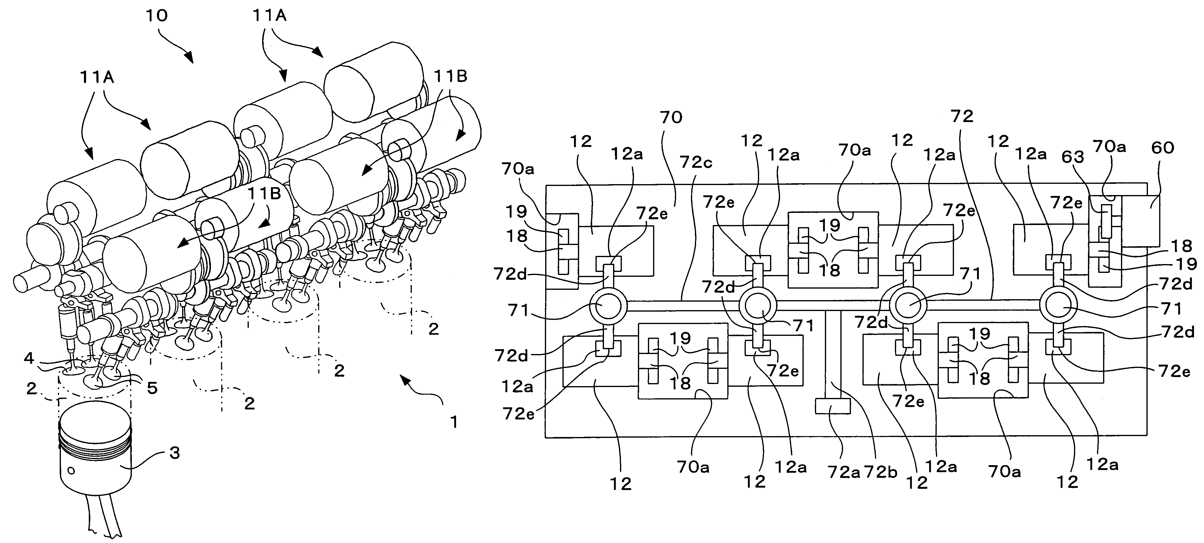
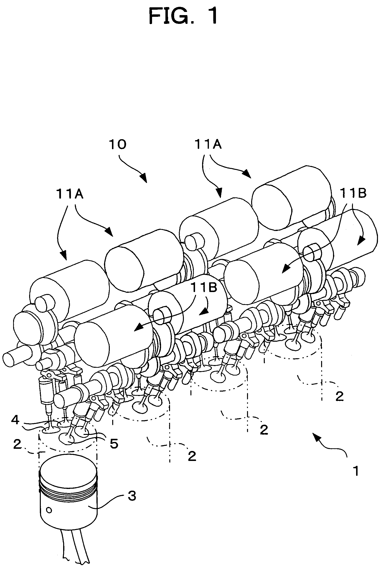
[0067]FIG. 1 shows an internal combustion engine 1 in which a valve-driving system according to the first embodiment of the present invention is incorporated. The internal combustion engine 1 is a multi-cylinder in-line gasoline engine. In the engine, a plurality of (four in FIG. 1) cylinders 2 . . . 2 are arranged in one direction, and pistons 3 are mounted in the respective cylinders 2 such that the pistons 3 can move vertically. Two intake valves 4 and two exhaust valves 5 are provided above each cylinder 2. These intake valves 4 and exhaust valves 5 are opened and closed by a valve-driving system 10 in association with vertical motion of the piston 3, thereby drawing air into the cylinder 2 and exhausting air from the cylinder 2.
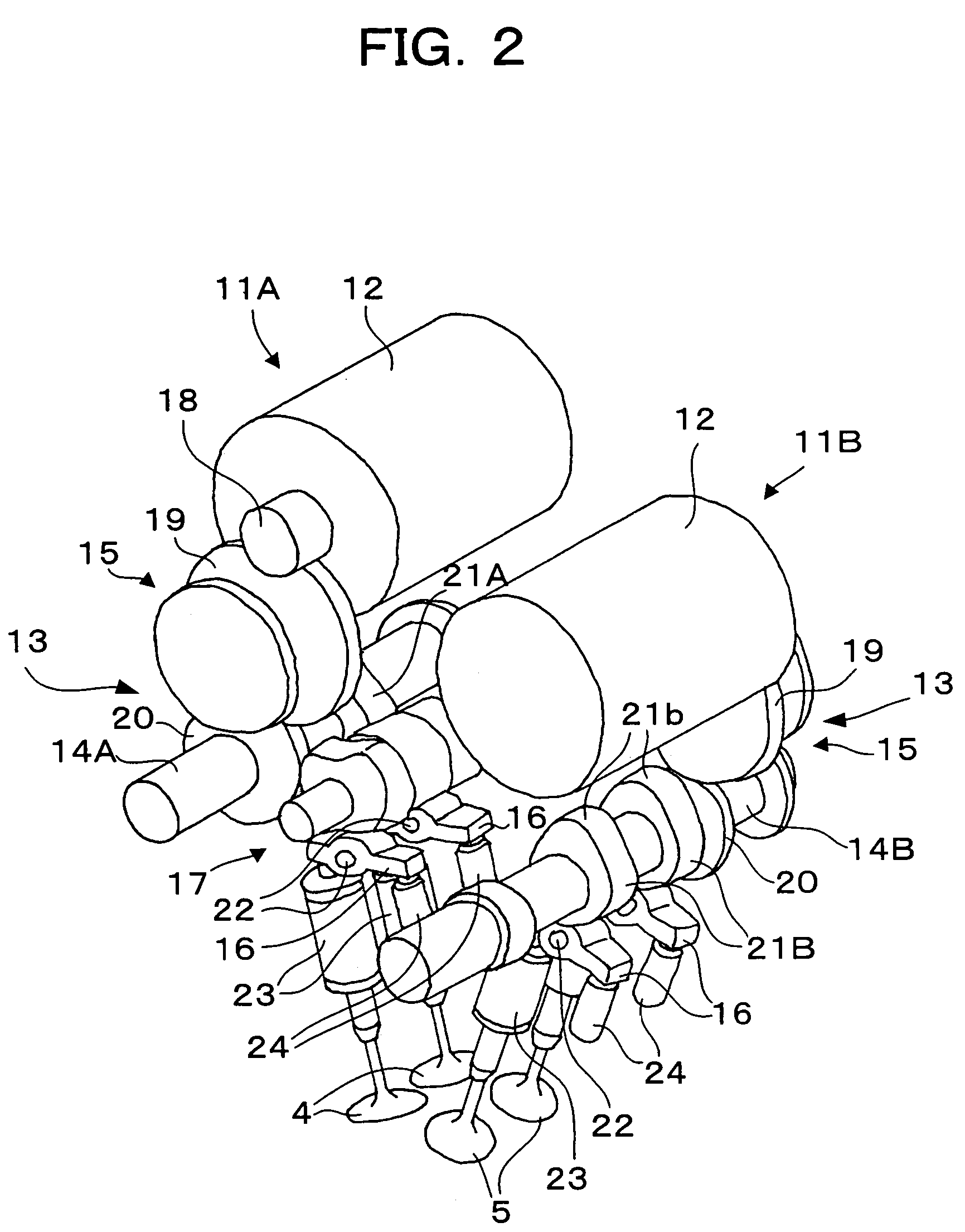
[0068]The valve-driving system 10 includes valve-driving apparatuses 11A . . . 11A provided on an intake-side of each cylinder 2 one each, and valve-driving apparatuses 11B . . . 11B provided on an exhaust-side of each cylinder 2 one each. The valve-driv...
second embodiment
[0128]FIGS. 18A and 18B and 19A to 19C show a valve-driving apparatus 11C according to the second embodiment of the present invention. This valve-driving apparatus 11C drives the intake valve 4 or the exhaust valve 5 utilizing a link. An example for driving the intake valve 4 will be explained here, but the same structure may be used for driving the exhaust valve 5.
[0129]The valve-driving apparatus 11C includes the electric motor 12 as a driving source, and a power transmission mechanism 100 which converts the rotation motion of the motor 12 into the opening and closing motion of the intake valve 4. The power transmission mechanism 100 includes an eccentric plate 101 as a rotation member which is rotated by the motor 12, a first link 103 which is rotatably connected to a connection position which is eccentric from the rotation center of the eccentric plate 101 through a connection pin 102, and a second link 105 which is rotatably connected to an upper end of the intake valve 4 throu...
third embodiment
[0136]FIGS. 20A, 20B and 20C show a valve-driving apparatus 11D according to the third embodiment of the present invention. This valve-driving apparatus 11D also drives the intake valve 4 or the exhaust valve 5 utilizing a link. Here, the valve-driving apparatus 11D drives the intake valve 4, but the same structure can be employed for driving the exhaust valve 5. In FIGS. 20A, 20B and 20C, the same members as those of the valve-driving apparatus 11D shown in FIGS. 18A and 18B are designated with the same reference signs.
[0137]The valve-driving apparatus 11D shown in FIGS. 20A, 20B and 20C includes the electric motor 12 as a driving source, and a power transmission mechanism 110 which converts the rotation motion of the motor 12 into the opening and closing motion of the intake valve 4. The power transmission mechanism 110 includes the eccentric plate 101 which is rotated by the motor 12, a first link111 rotatably connected, through a connection pin 102, to a connection position whic...
PUM
 Abstract
Description
Claims
Application Information
 - R&D
- Intellectual Property
- Life Sciences
- Materials
- Tech Scout
- Unparalleled Data Quality
- Higher Quality Content
- 60% Fewer Hallucinations
Browse by: Latest US Patents, China's latest patents, Technical Efficacy Thesaurus, Application Domain, Technology Topic, Popular Technical Reports.
© 2025 PatSnap. All rights reserved.Legal|Privacy policy|Modern Slavery Act Transparency Statement|Sitemap|About US| Contact US: help@patsnap.com


