Fuel injection apparatus

Active Publication Date: 2007-09-11
ROLLS ROYCE PLC
View PDF2 Cites 41 Cited by
  • Summary
  • Abstract
  • Description
  • Claims
  • Application Information

AI Technical Summary

Benefits of technology

[0006]Therefore an object of the present invention is to provide a means for reducing combustion instability and in particular reducing net heat release fluctuations within the combustor.

Problems solved by technology

Although LPP combustion systems can produce NOx emissions levels significantly lower than conventional combustion systems, there are severe disadvantages.
One of these is combustion instability.
The severity of the combustion instability produced varies from an irritating noise to a force powerful enough to stall gas turbine compressors and cause structural damage to combustion systems.

Method used


Image

  • Fuel injection apparatus
  • Fuel injection apparatus
  • Fuel injection apparatus

Examples


Embodiment Construction

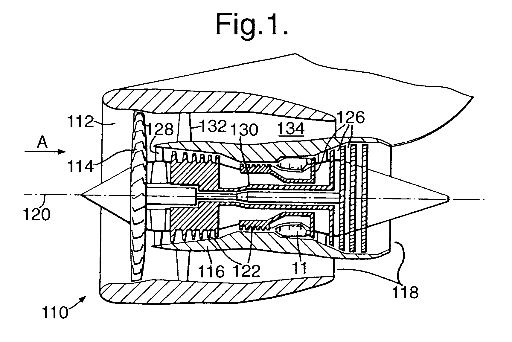
[0019]With reference to FIG. 1 a ducted fan gas turbine engine 110 comprises, in axial flow series an air intake 112, a propulsive fan 114, a core engine 116 and an exhaust nozzle assembly 118 all disposed about a central engine axis 120. The core engine 16 comprises, in axial flow series, a series of compressors 122, a combustor 124, and a series of turbines 126. The direction of airflow through the engine 110 in operation is shown by arrow A. Air is drawn in through the air intake 112 and is compressed and accelerated by the fan 114. The air from the fan 114 is split between a core engine flow and a bypass flow. The core engine flow passes through an annular array of stator vanes 128 and enters core engine 116, flows through the core engine compressors 122 where it is further compressed, and into the combustor 124 where it is mixed with fuel, which is supplied to, and burnt within the combustor 124. Combustion of the fuel mixed with the compressed air from the compressors 122 gene...


PUM


Abstract

A fuel injection apparatus (10) for a gas turbine engine (110) comprising a prefilmer (26), the prefilmer (26) comprises a body (50), the body (50) defines an axis (51), an annular surface (40) and a downstream edge (44), the prefilmer (26) arranged so that when working in operative association with the fuel injection apparatus (10) fuel impinges on the surface (40) and flows, by means of a passing airflow, to the downstream edge (44), from where the fuel is shed, characterized in that the fuel injector (10) further comprises a means for circumferentially varying the residence time of the fuel across the surface (40).

Description

[0001]This is a Continuation-in-Part National application Ser. No. 10 / 628,465 filed Jul. 29, 2003 now abandoned.FIELD OF THE INVENTION[0002]The present invention relates to a fuel injection apparatus for a combustor of a gas turbine engine and in particular a prefilmer thereof.BACKGROUND OF THE INVENTION[0003]There is an increasing demand to reduce the emissions produced by gas turbine combustors for aerospace, marine and industrial applications. One approach is to use lean premixed pre-vaporised (LPP) combustion in which liquid fuel is mixed and evaporated within a premixing duct. A typical LLP fuel injection apparatus is disclosed in EP0660038. The fuel-air mixture then flows into the combustion chamber where it is burnt. Low levels of oxides of nitrogen (NOx) emissions are obtained because the premixer produces a uniformly mixed fuel-air mixture at an equivalence ratio less than stoichiometric. This mixture burns at a relatively low flame temperature avoiding the NOx producing hi...

Claims


Application Information

Patent Timeline
IPC IPC(8): F02C7/22F23D11/10F23K5/22F23R3/28F23R3/32
CPCF23D11/101F23D11/107F23K5/22F23R3/286F23R3/32F23D2206/10F23D2900/11101F23K2301/205F23K2300/205
Inventor SANDERS, NOEL A.
Owner ROLLS ROYCE PLC
Why Eureka
Try Eureka