Signal identification method and apparatus for analogue electrical systems

a technology of analogue electrical systems and signal identification, applied in the direction of electric controllers, instruments, ignition automatic control, etc., can solve the problems of increasing the complexity of probing, increasing the difficulty of detecting the signal, so as to achieve good connection and improve the efficiency and accuracy of probing equipment.

Inactive Publication Date: 2007-09-04
GOOGLE LLC
View PDF7 Cites 10 Cited by
  • Summary
  • Abstract
  • Description
  • Claims
  • Application Information

AI Technical Summary

Benefits of technology

[0004]The present invention provides an apparatus, a method, and a computer program product for identifying signals in analogue electrical systems. This invention can be implemented to identify input signals, output signals, and bi-directional signals. Probing in complex digital systems is difficult, especially as physical dimensions decrease and packaging technologies become more miniature. By identifying the desired signal before probing it, the testing equipment can operate more efficiently and accurately. This invention enables the testing equipment to provide a good connection, ensures that the correct signals are being analyzed, and permits the testing equipment to “self-configure” based upon the type of analysis desired.

Problems solved by technology

In debugging and monitoring digital systems, the complexity of probing increases as the physical dimensions decrease and packaging technologies become more miniature.
Probing always creates some uncertainty as to what signal is being probed by the test equipment because the testing equipment must be attached to small, precise connections.
This is especially difficult if the probing process is manual.
Furthermore, with the complexity of digital systems, it is difficult to determine if the desired signals are being probed.
The analysis and measurements of the desired signals are inaccurate unless the complex testing equipment is connected to the complex digital system correctly.
This is due to the fact that the testing equipment may be analyzing the wrong signal or no signal at all.
Probing in complex digital systems is difficult for all types of test equipment.
Dedicated test equipment such as logic analyzers, oscilloscopes and counters, and hand held test equipment such as digital probes and multi-meters, experience the problems described above.
Probing in complex digital systems is difficult, especially as physical dimensions decrease and packaging technologies become more miniature.

Method used


Image

  • Signal identification method and apparatus for analogue electrical systems
  • Signal identification method and apparatus for analogue electrical systems
  • Signal identification method and apparatus for analogue electrical systems

Examples


Embodiment Construction

[0013]In the following discussion, numerous specific details are set forth to provide a thorough understanding of the present invention. However, those skilled in the art will appreciate that the present invention may be practiced without such specific details. In other instances, well-known elements have been illustrated in schematic or block diagram form in order not to obscure the present invention in unnecessary detail. Additionally, for the most part, details concerning network communications, electro-magnetic signaling techniques, and the like, have been omitted inasmuch as such details are not considered necessary to obtain a complete understanding of the present invention, and are considered to be within the understanding of persons of ordinary skill in the relevant art.

[0014]The present invention solves many of the problems involved with debugging and monitoring complex and miniature digital systems. First, probing typically creates some uncertainty that the probing connect...


PUM


Abstract

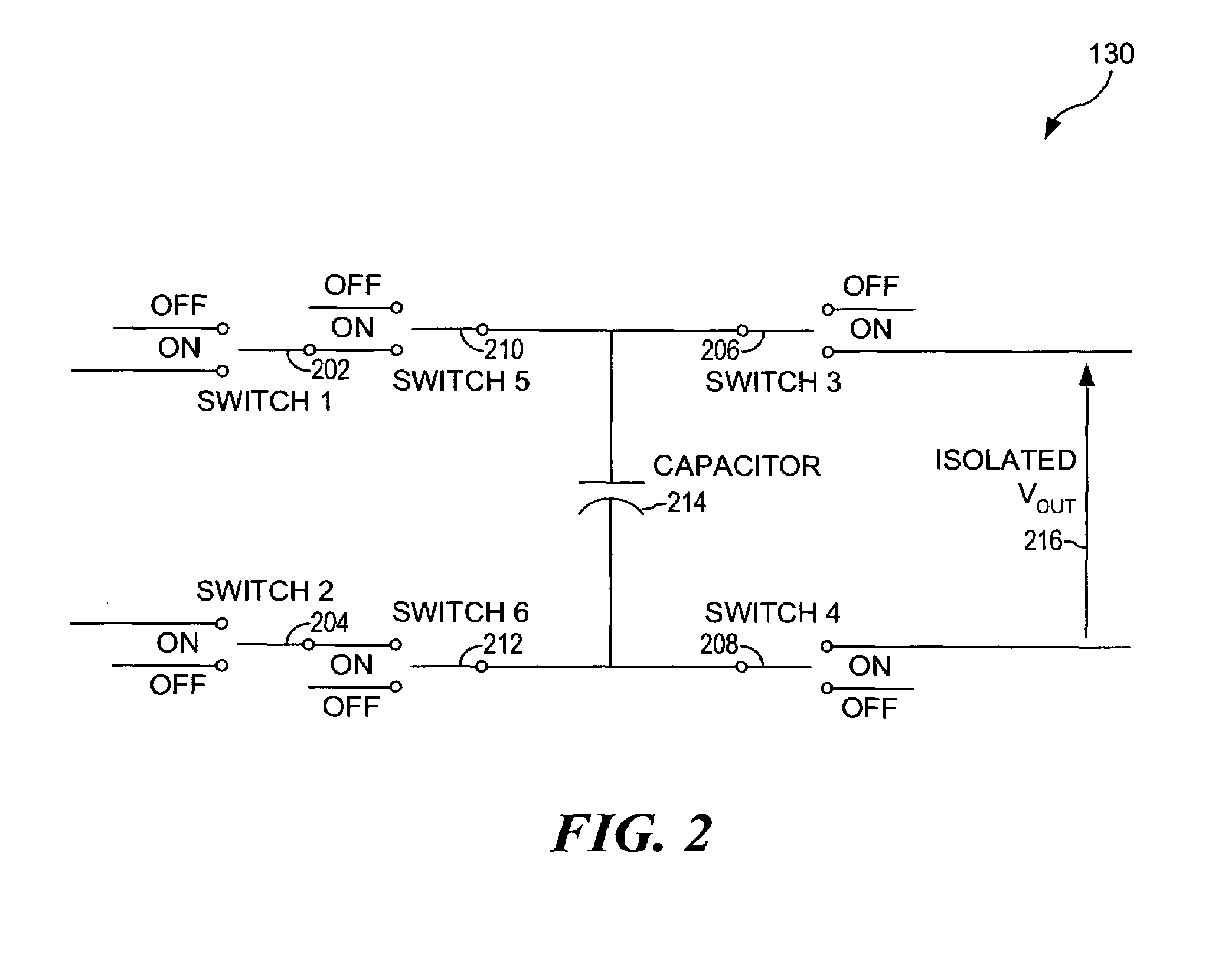
An apparatus, a method, and a computer program product are provided for identifying signals in analogue electrical systems. The ID select signals that control the timing of this signal identification circuit comprise sequential numbers that count up and identify a corresponding signal. The signals to be identified are located on a group of input / output (I / O) pins. One multiplexer (first) selects a specific I / O pin in response to the ID select signals. An isolated voltage source is connected to this multiplexer and provides the selected signal to another multiplexer (second). The second multiplexer switches from this isolated voltage source to ground potential in response to the ID select signals. The isolated voltage source floats at the DC level of the selected I / O driver pin. Therefore, by connecting to the selected signal's I / O pin and the output of the second multiplexer, the selected signal can be identified and then probed.

Description

FIELD OF THE INVENTION[0001]The present invention relates generally to a method of signal identification, and more particularly, to a method of signal identification for analogue electrical systems.DESCRIPTION OF THE RELATED ART[0002]In debugging and monitoring digital systems, the complexity of probing increases as the physical dimensions decrease and packaging technologies become more miniature. Probing always creates some uncertainty as to what signal is being probed by the test equipment because the testing equipment must be attached to small, precise connections. This is especially difficult if the probing process is manual. Furthermore, with the complexity of digital systems, it is difficult to determine if the desired signals are being probed. This process requires that the testing equipment is connected correctly. The analysis and measurements of the desired signals are inaccurate unless the complex testing equipment is connected to the complex digital system correctly. This...

Claims


Application Information

Patent Timeline
Patent Type & Authority Patents(United States)
IPC IPC(8): G01R19/00
CPCG01R31/3167G01R31/31924
Inventor DIXON, ROBERT CHRISTOPHERHARTFIEL, JOHN WAYNELE, HEIN MINHPHAM, TUNG NGUYEN
Owner GOOGLE LLC
Why Eureka
Try Eureka