
Automated palletizing cases having mixed sizes and shapes

a palletizing case and automatic technology, applied in the field of palletizing cases of various sizes, can solve the problems of shortening computer execution time and requiring a large number of decisions, and achieve the effects of ensuring the stability of stacked cases, minimizing processing time, and optimizing the use of pallet spa

Inactive Publication Date: 2007-09-04
FANUC ROBOTICS AMERCA
View PDF16 Cites 166 Cited by
  • Summary
  • Abstract
  • Description
  • Claims
  • Application Information

AI Technical Summary

Benefits of technology

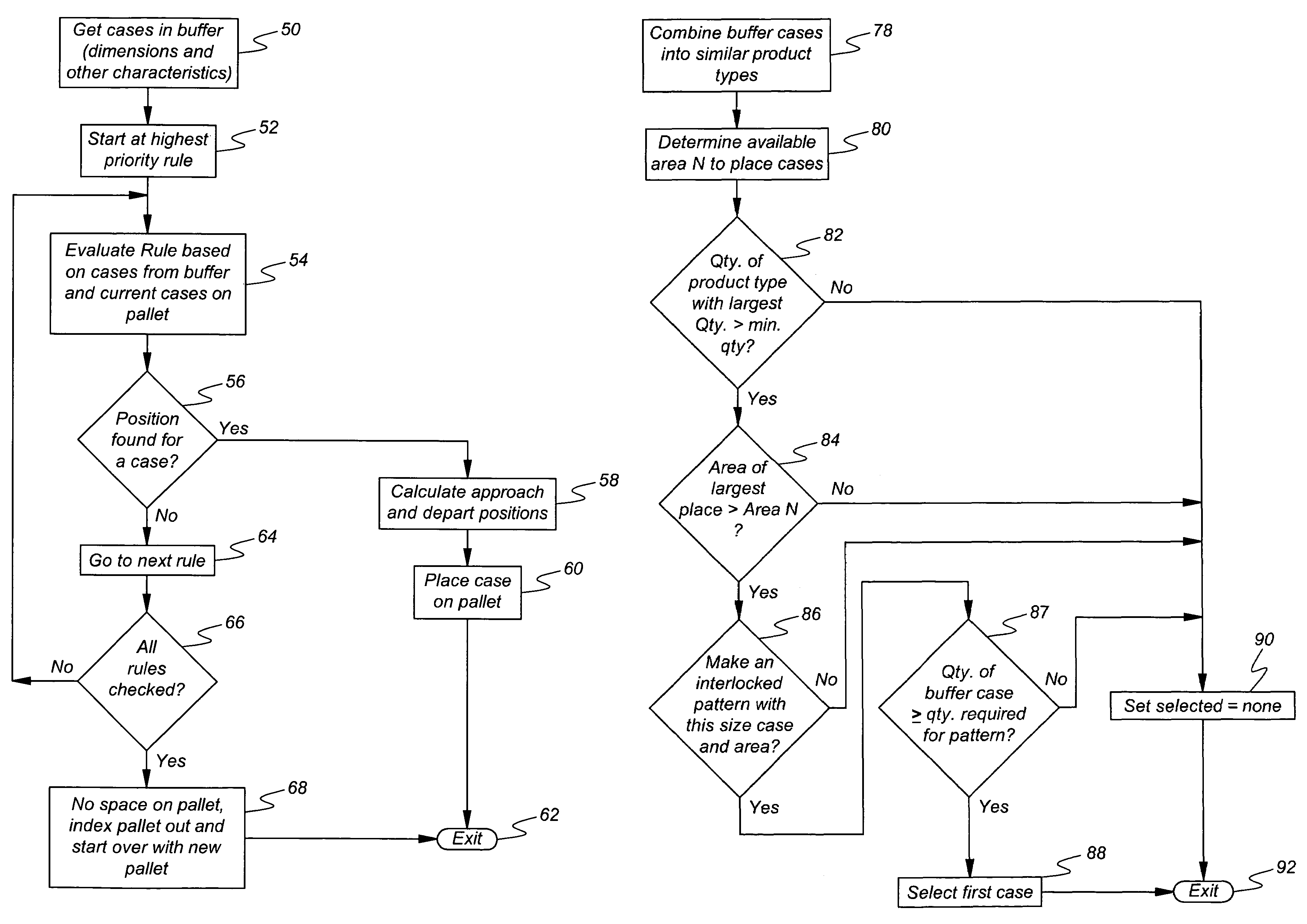
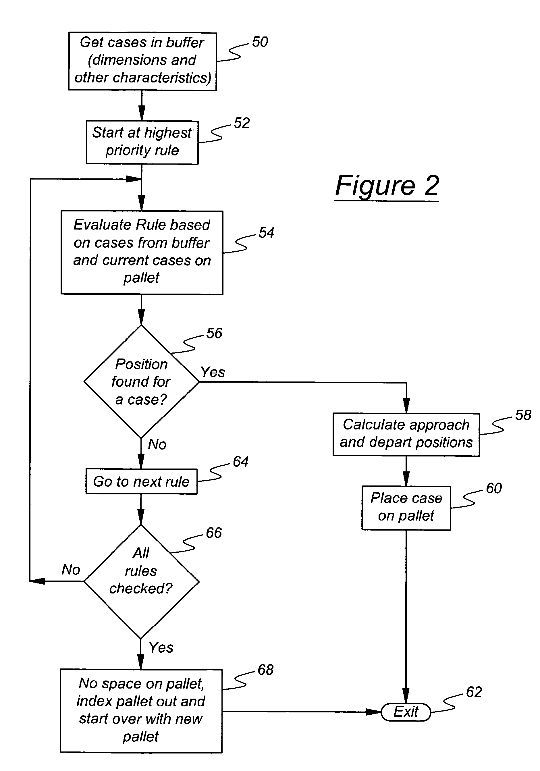
[0012]The method of this invention uses various methods or rules in a priority sequence to choose a case, or series of cases, for placement on a pallet. The rules achieve optimal use of space on the pallet and ensure stability of the stacked cases. For example, a Full Layer Rule is used when a group of cases having the same dimension would fill a vacant area of the pallet making a full layer, thereby creating a large flat surface for subsequent cases. A computer processor remembers for each rule each decision made in a prior occurrence of a group of cases in the buffer from which cases are selected for placement. This memory provision allows the control algorithm to use the rule so that processing time is minimized. For example, the Full Layer Rule calculates all of the positions for the layer and uses them in series until a current pallet the layer is filled completely.
[0014]Rather than maintain a simple three-dimensional representation of the pallet and placed boxes, a concept of regions is used to define the currently available places to place cases on the pallet. Each region is a plane on the pallet having an origin. The location of the origin expressed in X, Y, Z coordinates, and the planar dimensions of each region are retained by the computer. A case, preferably, is placed in one corner of the region, closest to pallet origin and farthest from the robot 14. The case can be placed at other corners of the region to maintain an even outside edge, to provide for better stability, or to utilize the available space in an efficient manner. Each place position for a case selected from the buffer 18 is located in a region. Each selected case has a corresponding region, place position in the region, and alignment or arrangement of the selected case in the region. This ensures the rules of selection and placement will produce an efficiently loaded, stable pallet. The use of regions reduces the number of potential place positions, the number of decisions required while executing the algorithms, and shortens computer execution time. The execution time required by a method according to this invention is less than 50 m-sec per case, compared to 100-500 m-sec per case using conventional, commercially available methods.

Problems solved by technology

If a case or a stack of cases, sometimes called a tower, would be unstable during pallet conveyance, the case is not placed.
The use of regions reduces the number of potential place positions, the number of decisions required while executing the algorithms, and shortens computer execution time.

Method used


Image

  • Automated palletizing cases having mixed sizes and shapes
  • Automated palletizing cases having mixed sizes and shapes
  • Automated palletizing cases having mixed sizes and shapes

Examples


Embodiment Construction

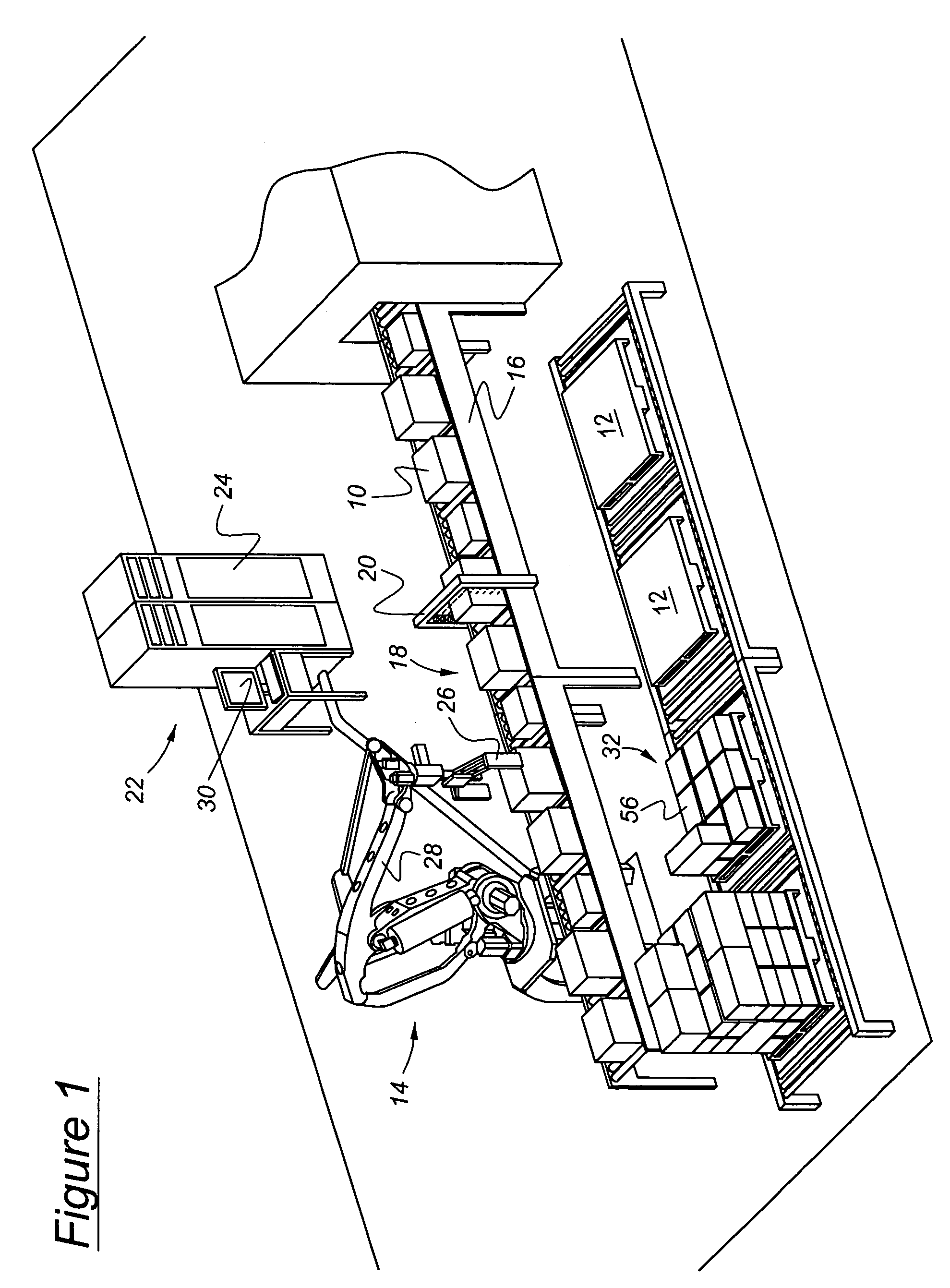
[0028]A representative arrangement of the equipment used to stack cases 10 on pallets 12 using an industrial robot 14 controlled according to this invention is shown in FIG. 1. Cases 10 are transported in a random sequence of mixed sizes, shapes, weight and content, etc. on a conveyor 16, which delivers the cases to a buffer or queue 18 containing cases located within the range of access of the robot arm 14, which lifts cases from the buffer and places them on a pallet under computer control. This process is referred to as automated palletizing.

[0029]The cases 10 pass through a scanner 20, such as bar code reader, which scans the outer surfaces of the cases and reads a UPC bar code located there. Information obtained by reading the bar code is conveyed to a computer system 22, which determines with reference to the bar code information in a database stored in electronic memory accessible to the computer processor. The information preferably includes, but is not limited to dimensions...


PUM


Abstract

A method for stacking cases on a pallet includes supplying cases to a buffer, determining physical characteristics of buffer cases including dimensions of a case base and case height, and determining available positions on the pallet where a buffer case can be placed. Rules for selecting a case from the buffer for placement on the pallet are applied to at least a portion of the buffer cases to identify a selected buffer case that satisfies at least one of the rules and a corresponding place on the pallet for the selected case. Then the selected case is removed from the buffer and placed on the pallet in the corresponding place by an industrial robot.

Description

BACKGROUND OF THE INVENTION[0001]1. Field of the Invention[0002]This invention relates to stacking cases of various size, shape, and weight on a pallet for transport. More particularly the invention pertains to a computer-controlled method for selecting cases presented in random order and using an industrial robot to produce a stable stack of cases on the pallet.[0003]2. Description of the Prior Art[0004]In the transportation and distribution of goods, cases, boxes or cartons containing goods are stacked on a portable platform or pallet that is readily moved by a vehicle from a palletizing area. The cases frequently vary in size, shape, and weight and usually arrive in a random order in the area where they are placed on the pallets. This usually results in a random stacking of the cases until the pallet is either completely full or cannot be stacked higher. The pallets are usually then enveloped by shrink-wrap plastic material to prevent inadvertent displacement of the cases during ...

Claims


Application Information

Patent Timeline
Patent Type & Authority Patents(United States)
IPC IPC(8): G06F7/00
CPCB25J9/1687B65G61/00B65G2201/025G05B2219/31312G05B2219/31313G05B2219/40007G05B2219/40067G05B2219/45056G05B2219/50364Y02P90/02
Inventor DEMOTTE, DONALDPOMA, MIKEMONIQUE, ANDREW
Owner FANUC ROBOTICS AMERCA
Learn More