
Methods, systems and apparatuses for automated irrigation and chemical treatment

a technology of automatic irrigation and chemical treatment, applied in the field of lawn care systems, can solve the problems of inability to gauge whether the subject field is sufficiently saturated, inability to save water, so as to reduce or eliminate reduce or eliminate the effect of redundant or inadequate chemical applications

Inactive Publication Date: 2007-09-04
INTELLIGENT LAWN SYST
View PDF36 Cites 87 Cited by
  • Summary
  • Abstract
  • Description
  • Claims
  • Application Information

AI Technical Summary

Benefits of technology

[0008]The present invention provides improvements in automated irrigation and chemical treatment systems in a low cost, efficient manner. The system of the present invention is easily programmable and accommodates sprinkler head level data acquisition to provide customized water and chemical delivery to individually zoned areas of a land region.
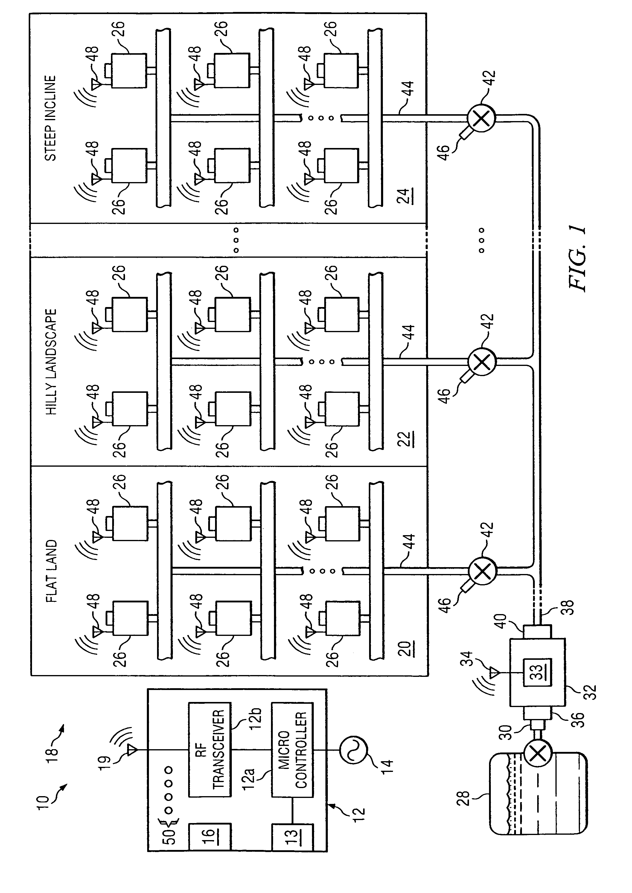
[0009]The system of the present invention also provides improvements in water saturation testing, proper mixing of chemicals to provide adequate lawn fertilization, weed control and pesticide application without user intervention. The system of the present invention further provides an automated system that includes, for example, a control unit, mixing chamber, sprinkler heads and valves that communicate with each other. Thus, the user of the system need not worry about “day-to-day” operations.
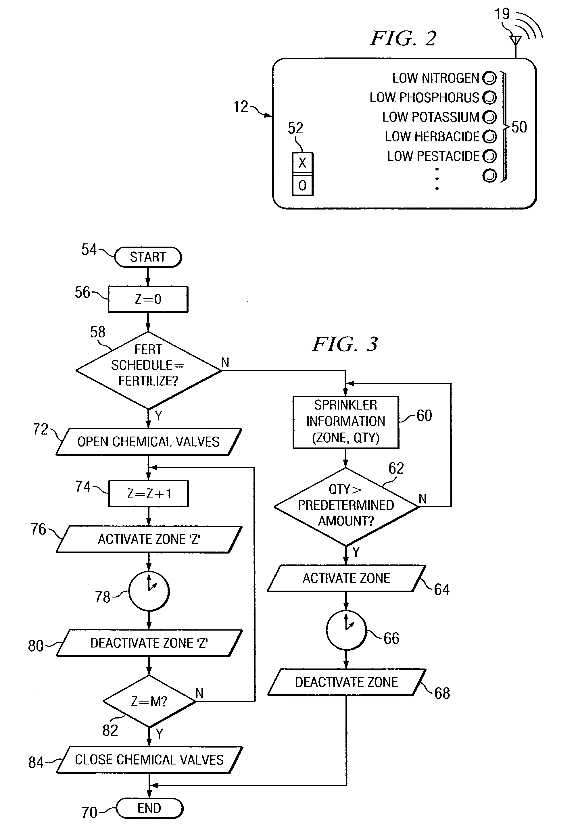
[0010]The system of the present invention still further provides an irrigation system which includes various chemical containers to house, for example, fertilizers, herbicides and pesticides that are eventually delivered to a zoned area at regularly scheduled intervals, or alternatively, when soil sensors indicate that a zoned area requires such chemicals. The present invention, thus, will reduce or eliminate redundant or inadequate chemical application to a zoned area while controlling unnecessary chemical pollution into water supplies and minimizing human contact with such chemicals. Accordingly, the system of the present invention reduces unnecessary water and chemical consumption, thus lowering watering and chemical treatment costs for the consumer.
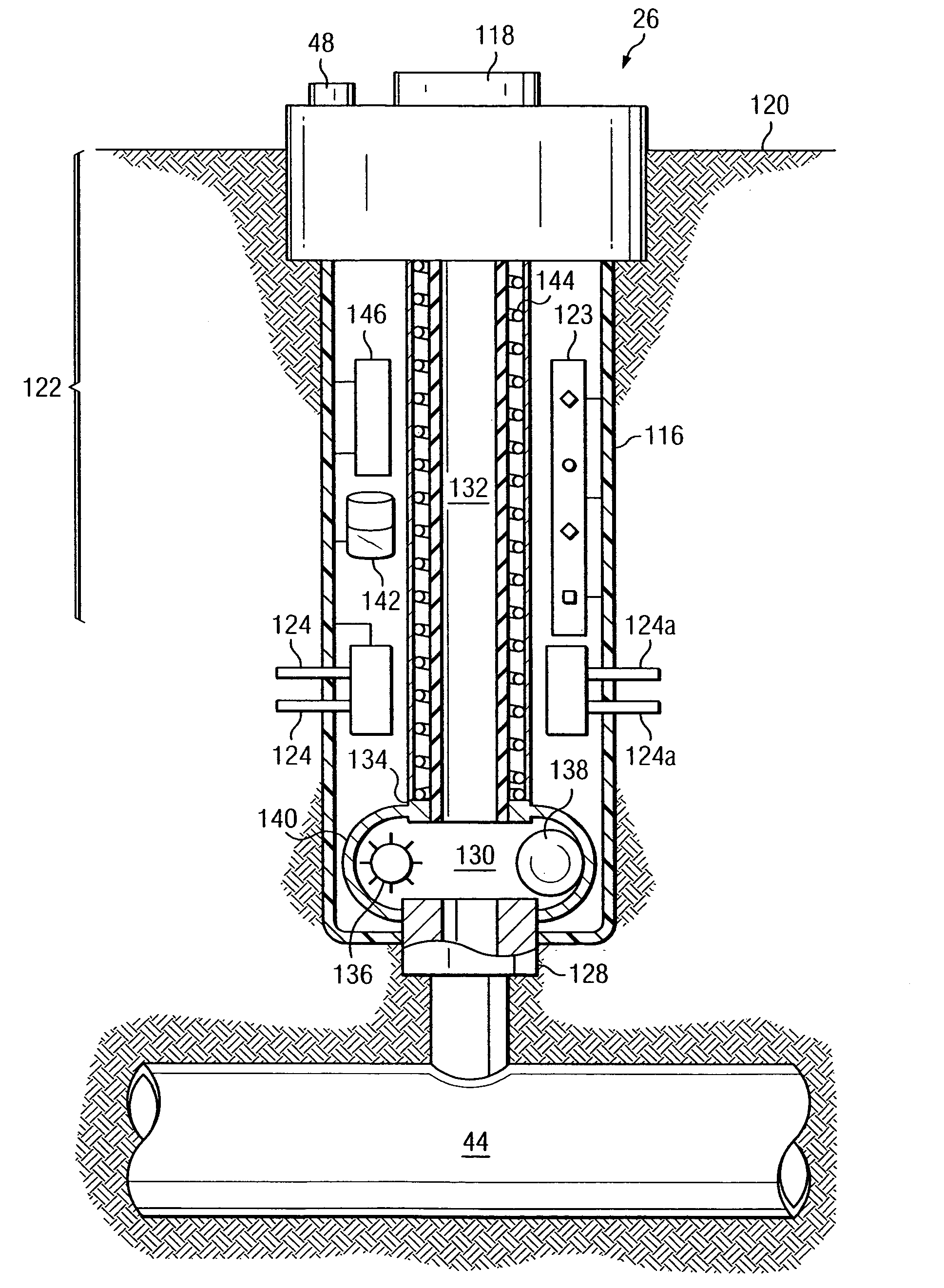
[0011]The present invention still further provides an irrigation sprinkler head which includes a unique plunger system within the sprinkler head that controls the flow of water and / or other fluids out of the sprinkler head. The system of the present invention still further provides strategically placed energy capturing devices that utilize energy from the flow of liquid and the inherent water pressure subsisting within the system to charge rechargeable batteries and to drive certain parts of the system, thus, providing a self sustained, energy efficient system.

Problems solved by technology

Some systems lack the ability to gauge whether the subject field is already saturated before irrigation begins.
Thus, these systems fail to conserve water and often times over saturate the subject field and foster unfavorable and sometime harmful conditions, such as disease or molding.
Other systems lack the ability to gauge whether the subject field has been adequately saturated after distributing water.
Often times, these systems fail to provide the subject field with enough water, leaving the field to dry out and eventually die.
These systems unnecessarily employ a large database and assume evapotranspiration rates will remain relatively constant year to year.
These systems further fail to recognize geological deviations in the land itself, including failing to recognize that some parts of the land may be more conducive to drainage than are others.
Furthermore, the current systems require costly deployment mapping in order to locate and replace buried sensors.
Thus, these systems often end up fertilizing the entire land regardless of whether a necessity exists.
Thus, known sprinkler heads fail to accommodate topographical gradients, existing environmental conditions and other factors within a controlling zone.

Method used


Image

  • Methods, systems and apparatuses for automated irrigation and chemical treatment
  • Methods, systems and apparatuses for automated irrigation and chemical treatment
  • Methods, systems and apparatuses for automated irrigation and chemical treatment

Examples


Embodiment Construction

[0024]In the description that follows, like elements are marked throughout the specification and drawings with the same reference numerals, respectively. The drawing figures are not necessarily to scale and certain elements may be shown in somewhat generalized or schematic form in the interest of clarity and conciseness. Certain routine steps, in flow charts, normally included in the operation of the present invention have been omitted in the interest of conciseness. However, the steps which include methodology in accordance with the present invention are indicated in the charts. As is conventional, the letters Y and N designate “yes” and “no”, respectively.

[0025]The automated irrigation and chemical treatment system 10 of the present invention, depicted in FIG. 1, is controlled by a user programmable control unit 12 which includes a programmable micro controller 12a operably connected to a suitable wireless transmitter / receiver unit 12b. A user may program the control unit 12 via a...


PUM


Abstract

An automated irrigation and chemical treatment system comprising a user input device adapted to communicate with a control unit; a mixing chamber adapted to communicate with the control unit and connected to a water supply and chemical canisters, wherein each canister has a sensor to monitor fluid level therein, and control valves for connecting the mixing chamber to a network of pipes. Sprinkler heads connected to the network of pipes each include, a control valve adapted to control fluid flow to a water delivery nozzle by an electro magnet controlled rubber coated ferric ball closure member. The sprinkler heads include water and chemical saturation sensors and the sprinkler heads also communicate with the control unit via wireless transceivers. Multiple zones covered by the system may be treated according to predetermined schedules.

Description

BACKGROUND[0001]The present invention relates to the general field of irrigation and lawn care systems, and in particular, to automated irrigation and chemical treatment systems.[0002]Irrigation systems for residential and commercial applications, known in the art, often include a centralized control switch that triggers watering during specified time frames. Some systems lack the ability to gauge whether the subject field is already saturated before irrigation begins. Thus, these systems fail to conserve water and often times over saturate the subject field and foster unfavorable and sometime harmful conditions, such as disease or molding. Other systems lack the ability to gauge whether the subject field has been adequately saturated after distributing water. Often times, these systems fail to provide the subject field with enough water, leaving the field to dry out and eventually die. What is needed is an irrigation system that automatically allocates water, only if necessary, aft...

Claims


Application Information

Patent Timeline
Patent Type & Authority Patents(United States)
IPC IPC(8): B05B12/08A01G25/00A01G27/00B05B7/26B05B15/10G05D11/00G05D7/00
CPCA01C23/042A01G25/16A01M7/0092Y10S239/15Y10T137/189
Inventor BUCK, DAVID AARONSTOREY, THOMAS DANIELBUCK, RICHARD DAVID
Owner INTELLIGENT LAWN SYST
Learn More