
Flow control in network devices

a network device and flow control technology, applied in data switching networks, high-level techniques, frequency-division multiplexes, etc., can solve the problems of non-responsive flows that can “choke out” responsive flows, taking all the excess bandwidth, etc., and achieve the effect of reducing the deviation

Inactive Publication Date: 2007-08-21
IBM CORP
View PDF7 Cites 13 Cited by
  • Summary
  • Abstract
  • Description
  • Claims
  • Application Information

AI Technical Summary

Benefits of technology

[0009]varying at least one adjustment parameter for at least one flow of at least one of said sets in dependence on the error signal so as to reduce said deviation.
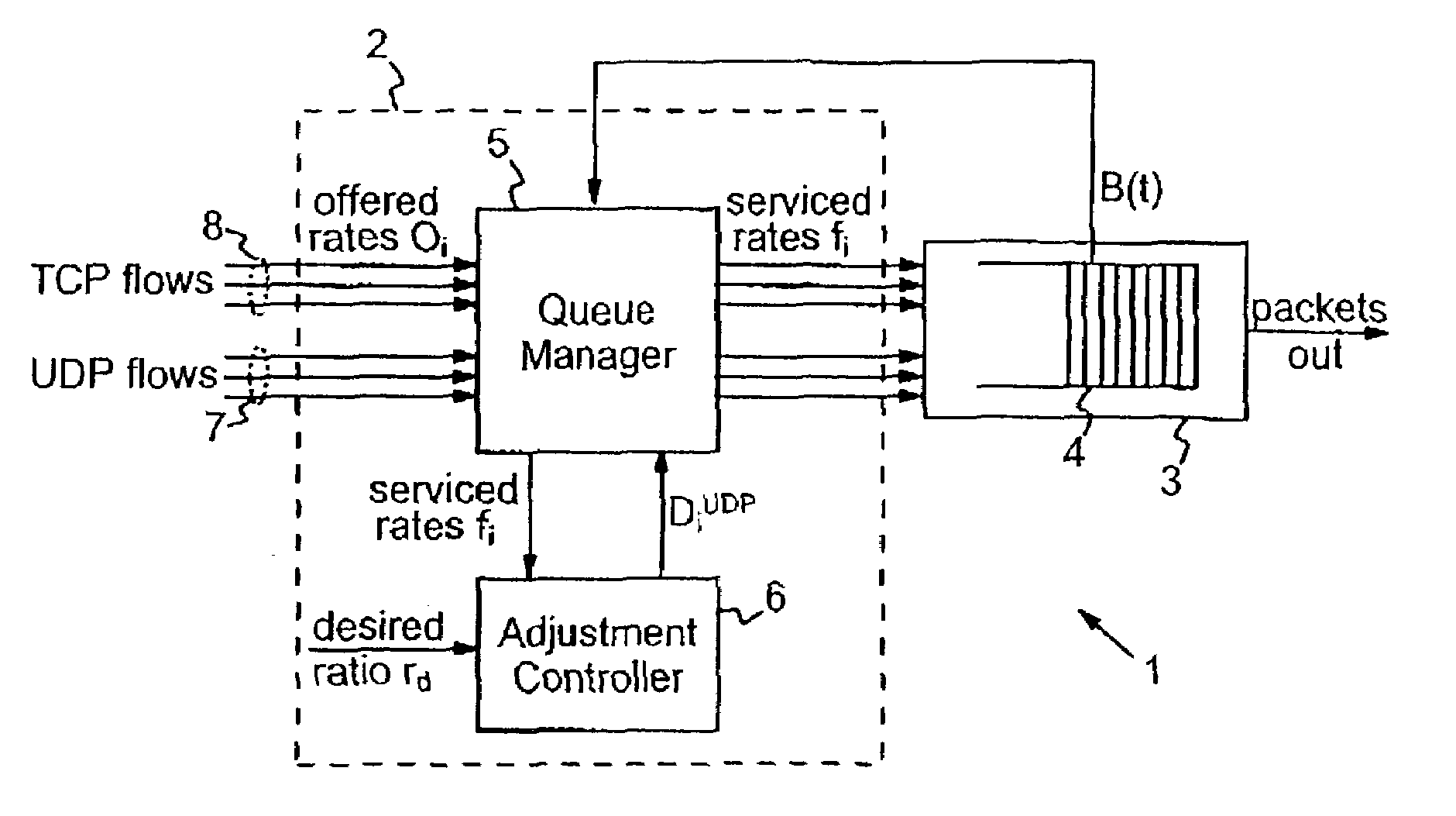
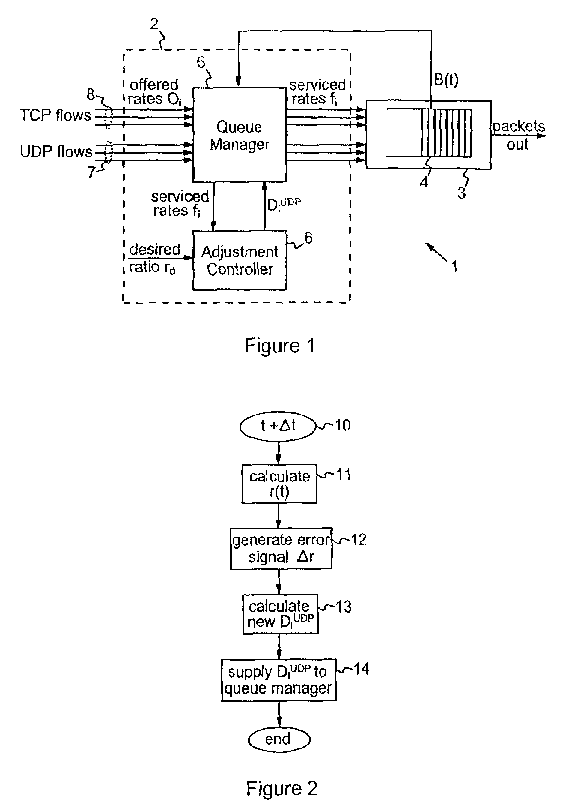
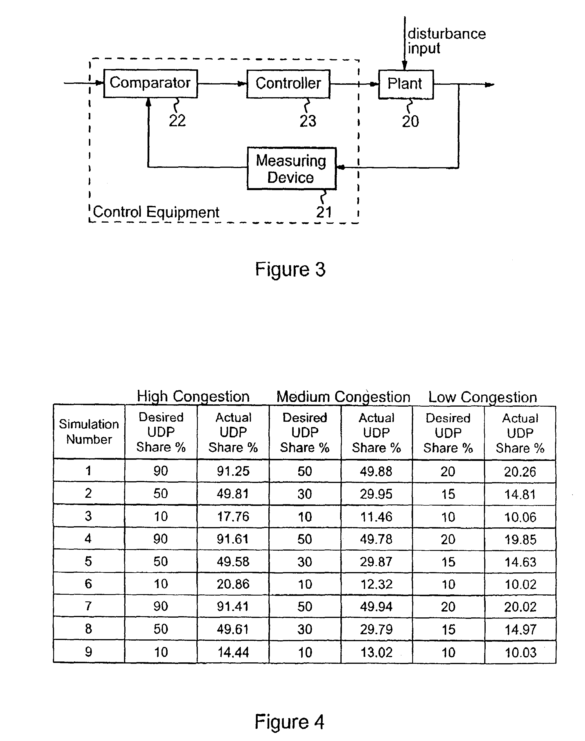
[0010]Thus, methods embodying the invention control flow rates into a queue (i.e. the serviced rates) for a plurality of flows which comprises a set of non-responsive flows and a set of other flows. Each set may comprise one or more flows, so in the limiting case the method may operate for only two flows. The first set comprises flows which are known to be non-responsive. The second set comprises other flows. These other flows may be those flows which are known to be responsive flows. However, the responsiveness of all flows handled by the flow control system may not be known in all embodiments. In such cases the second set may include those flows whose responsiveness is unknown. In general, therefore, the second set may comprise those flows which are not known to be non-responsive. In any case, the serviced rates for the flows are controlled via a queue management scheme which adjusts flow rates based on bandwidth availability, each flow rate being adjusted by amounts dependent on one or more adjustment parameters for that flow. During operation of the queue management process, an error signal is generated based on the difference between a desired allocation ratio and the ratio of the total serviced rates for the two flow-sets. This error signal thus provides an indication of the deviation of the bandwidth allocation between the two sets of flows from a desired value. The error signal is then used to vary at least one of the adjustment parameters used in the queue management process in such a manner as to reduce this deviation. Thus, embodiments of the invention provide a closed-loop control scheme, operating in conjunction with an underlying queue management scheme, which alleviates the problem caused by non-responsive flows discussed above. Fair bandwidth allocation can thus be achieved in embodiments of the invention even in difficult traffic situations where a mix of both non-responsive and responsive flows must be managed. Overall, therefore, methods embodying the invention offer significantly improved flow control compared to prior systems.
[0013]In general, depending on the particular adjustment parameters employed in the queue management scheme, one or more adjustment parameters for one or more flows may be varied in dependence on the error signal. In preferred embodiments, simplicity of operation combined with particularly effective control of the overall bandwidth allocation is achieved by varying at least one adjustment parameter for each flow of only one of said sets. Most preferably, a single adjustment parameter is varied for each flow of only one of said sets. In the particularly preferred embodiments described below, the queue management process is performed according to the BAT scheme wherein each flow rate is increased by an amount dependent on an increase parameter when excess bandwidth is available, and decreased by an amount dependent on a decrease parameter when excess bandwidth is not available. Particularly efficient operation is achieved in these preferred embodiments by varying the decrease parameter for each flow of the set of non-responsive flows.
[0017]an adjustment controller for controlling at least one adjustment parameter for at least one flow of at least one of said sets, the adjustment controller being arranged to generate an error signal dependent on the deviation from a desired allocation ratio of the ratio of the total flow rates into the queue for said sets of flows, and to vary said at least one adjustment parameter in dependence on the error signal so as to reduce said deviation.

Problems solved by technology

This means that non-responsive flows can “choke out” responsive flows, taking all the excess bandwidth at the local level.
This is directly contrary to the underlying objective of achieving fair bandwidth allocation between all flows handled by the queue management system.

Method used


Image

  • Flow control in network devices
  • Flow control in network devices
  • Flow control in network devices

Examples


Embodiment Construction

[0033]Flow control systems embodying the invention may be employed in a variety of network devices such as switches, routers, bridges, traffic shapers, load balancing devices, middleboxes, and devices incorporating firewalls for example. In general the flow control systems to be described may be employed in any device in which management of queues is required. In a typical network device such as a router, incoming data packets received by the device undergo various processing stages, for example buffering in the medium access control components, packet classification and transmission across the internal switching fabric, before being forwarded on across the network. Packets may be queued at various stages of this process pending processing by a particular device resource. Flow control systems embodying the invention can be employed at any one of these stages to protect the resource from overload under conditions of congestion. A particular example of such a flow control system will ...


PUM


Abstract

Methods and apparatus are provided for controlling flow rates of a plurality of data packet flows into a queue 4 corresponding to a resource 3 of a network device 1. The flows comprise a set 7 of non-responsive flows, and a set 8 of other flows which may comprise responsive flows and / or flows whose responsiveness is unknown. The flow rates are managed in accordance with a queue management scheme such that adjustments are made to each flow rate in dependence on excess bandwidth in the resource, the amounts of the adjustments being dependent on one or more adjustment parameters for each flow. An error signal is generated based on the deviation from a desired allocation ratio of the ratio of the total flow rates into the queue 4 for the sets of flows 7, 8. At least one adjustment parameter for at least one flow is then varied in dependence on the error signal in such a manner as to reduce the aforementioned deviation. A closed-loop control scheme thus operates in conjunction with the underlying queue management scheme to promote fair bandwidth allocation even in the presence of a mix of responsive and non-responsive flows.

Description

TECHNICAL FIELD[0001]This invention relates generally to flow control in data communications networks, and more particularly to methods and apparatus for controlling flow rates into data packet queues in network devices.BACKGROUND OF THE INVENTION[0002]When any resource of a network device involved in the processing of data packets receives packets at a higher rate than it can process the packets, then packets will back up, effectively giving rise to a queue of data packets. Flow control mechanisms are generally provided to manage the transmission into the queue of data packets from various flows, where a “flow” is some defined set or category of data packets, such as packets from a particular group of sources, or conforming to a particular protocol, or packets requiring a particular class of service for example. In particular, queue management schemes can be implemented to control the flow rate into the queue (i.e. the enqueuing rate or “serviced rate”) for each flow according to t...

Claims


Application Information

Patent Timeline
Patent Type & Authority Patents(United States)
IPC IPC(8): H04J1/16H04J3/16H04L12/28H04L12/66H04L12/56
CPCH04L47/10H04L47/193H04L47/2416H04L47/29H04L47/30H04L47/263Y02B60/31H04L47/38H04L47/24H04L47/525Y02D30/50
Inventor BOWEN, JR., HOYT EDWINDROZ, PATRICKJEFFRIES, CLARK D.KENCL, LUKASKIND, ANDREASMANNAL, SOENKE V.PLETKA, ROMAN A.
Owner IBM CORP
Learn More