
Method and apparatus for driving liquid crystal display

Active Publication Date: 2007-08-21
LG DISPLAY CO LTD
View PDF13 Cites 22 Cited by
  • Summary
  • Abstract
  • Description
  • Claims
  • Application Information

AI Technical Summary

Benefits of technology

[0018]Accordingly, an advantage of the present invention provides a method and apparatus for driving a liquid crystal display capable of enhancing a display quality and reducing power consumption.

Problems solved by technology

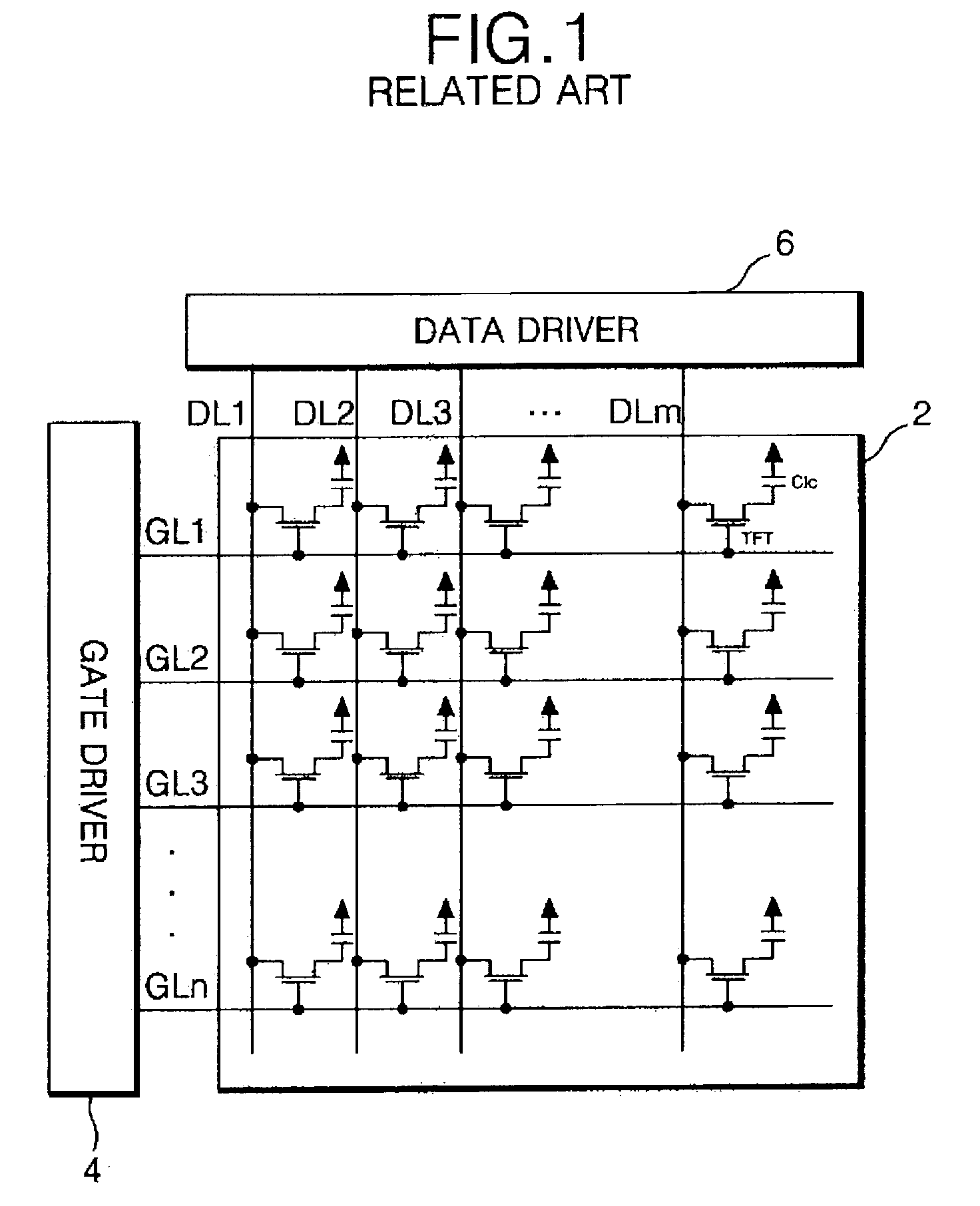
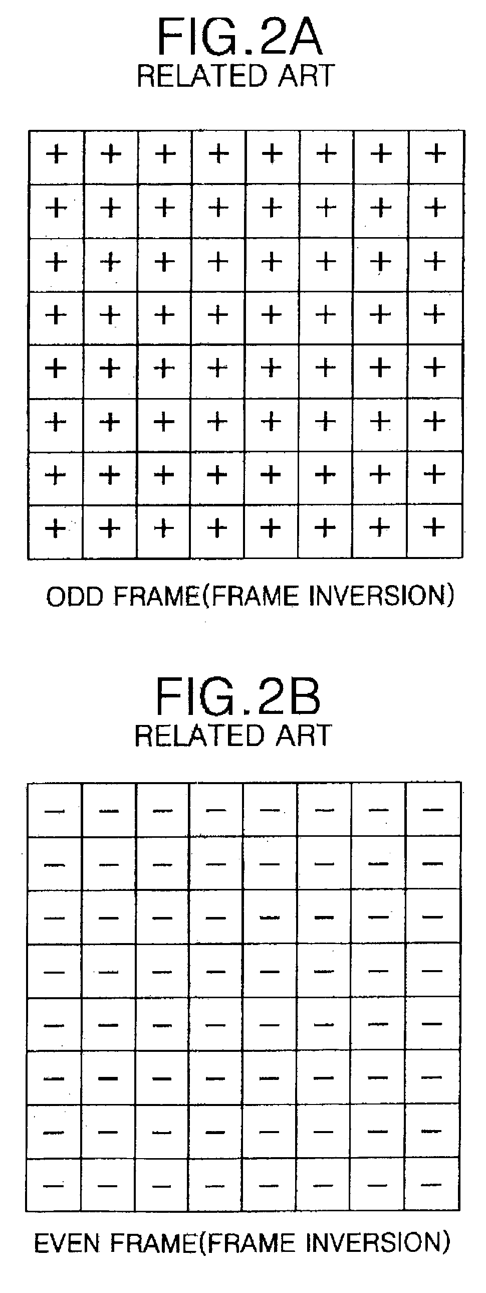
Driving liquid crystal cells by the frame inversion system, however, is disadvantageous in that a flicker phenomenon is induced due to variations in voltage charged within the liquid crystal cells between frames is large.
Driving liquid crystal cells by the line inversion system, however, is disadvantageous in that a flicker phenomenon is induced in horizontal lines due to electrical cross-talk between liquid crystal cells arranged along the gate lines.
Driving liquid crystal cells by the column inversion system, however, is disadvantageous in that a flicker phenomenon is induced in vertical lines due to electrical cross-talk between liquid crystal cells arranged along the data lines.
Use of the dot inversion system, however, is disadvantageous in that the polarity of voltage of the video signals supplied from the data driver to the data lines is inverted in horizontal and vertical directions and individual pixel voltages required by the dot inversion method are typically greater than those required by other inversion methods.
Accordingly, liquid crystal displays driven using a dot inversion method typically consume a relatively large amount of power during their operation.

Method used


Image

  • Method and apparatus for driving liquid crystal display
  • Method and apparatus for driving liquid crystal display
  • Method and apparatus for driving liquid crystal display

Examples


Embodiment Construction

[0072]Reference will now be made in detail to embodiments of the present invention, examples of which are illustrated in the accompanying drawings.

[0073]FIG. 6 illustrates a schematic view of a liquid crystal display (LCD) according to a first aspect of the present invention.

[0074]Referring to FIG. 6, the LCD may, for example, include a liquid crystal display panel 12 having a plurality of liquid crystal cells arranged in a matrix pattern, a gate driver 14 for driving gate lines GL1 to GLn arranged on the liquid crystal display panel 12, a data driver 16 for driving successively arranged data lines DL1 to DLm+1 also arranged on the liquid crystal display panel 12, and a timing controller 18 for controlling the gate and data drivers 14 and 16, respectively.

[0075]The liquid crystal display panel 12 may, for example, comprise an upper glass substrate and a lower glass substrate separated from each other by a layer of liquid crystal material (not shown). The liquid crystal display panel...


PUM


Abstract

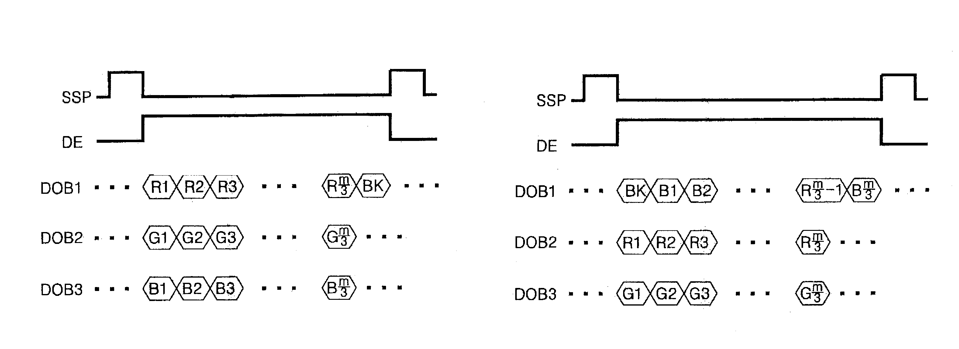
A method and apparatus for driving a liquid crystal display enhances display quality and reduces power consumption. A portion of inputted data may be reproduced and used in the generation of dummy data. A scanning pulse is applied to gate lines of a liquid crystal display panel supporting lines crossing the gate lines. Consecutive ones of thin film transistors within columns of liquid crystal calls may be alternately coupled to adjacent ones of data lines. The inputted data and the dummy data are applied to the data lines in synchrony with the scanning pulse.

Description

[0001]This application claims the benefit of Korean Patent Application No. 2002-21795 filed on Apr. 20, 2002, which is hereby incorporated by reference for all purposes as if fully set forth herein.BACKGROUND OF THE INVENTION[0002]1. Field of the Invention[0003]The present invention relates to a liquid crystal display, and more particularly to a method and apparatus driving a liquid crystal display capable of enhancing display quality and reducing power consumption.[0004]2. Discussion of the Related Art[0005]Generally, liquid crystal displays LCDs include a liquid crystal display panel having a plurality of liquid crystal cells arranged in a matrix pattern and driving circuit for driving the liquid crystal display panel. To display images, liquid crystal displays control light transmittance characteristics of each liquid crystal cell in accordance with an inputted video signal. Active matrix LCDs include a plurality of thin film transistors (TFTs) arranged within each liquid crystal...

Claims


Application Information

Patent Timeline
IPC IPC(8): G09G3/36G02F1/133
CPCG09G3/3688G09G3/3607G09G3/3614G09G2330/021G02F1/133
Inventor YUN, SANG CHANGPARK, JUNE HOLEE, JAE WOO
Owner LG DISPLAY CO LTD
Learn More