
Personal propulsion device

a propulsion device and personal technology, applied in the field of powered flight, can solve the problems of low power-to-weight ratio of human beings, severe limits on operation duration and range, and close proximity of propellers, rotor blades, rocket exhaust to the pilot, etc., and achieve the effect of providing inherent stability

Active Publication Date: 2007-08-21
ZAPIP LLC
View PDF27 Cites 84 Cited by
  • Summary
  • Abstract
  • Description
  • Claims
  • Application Information

AI Technical Summary

Benefits of technology

The solution provides a safer, more stable, and efficient flight experience with improved power-to-weight ratio, enabling vertical takeoff and landing, increased maneuverability, and longer range and duration.

Problems solved by technology

However, unlike birds, human beings have a low power-to-weight ratio, and personal flight has only been accomplished by developing machines using powerful engines and aerodynamic lifting surfaces, such as autogyro aircraft, fixed wing airplanes, and helicopters.
In addition to having a reservoir of volatile fluid attached to the body of a pilot, the close proximity of the propeller, rotor blades, or rocket exhaust to the pilot further poses significant safety risks.
Another drawback of such self-contained, single-passenger flight packs is that the pilot must support the entire weight of both the airframe and fuel on his back, which can be highly uncomfortable and places severe limits on operation duration and range.
Moreover, the location of thrust forces and the weight distribution of the fuel and accompanying components in such designs increase instability during take-off and for the duration of the flight.
Existing single passenger devices suffer an additional major drawback, in that the fuselage, engine, electrical equipment, fuel, and flight instrumentation are all part of the aircraft.
As a result of the added weight of these systems, a significant amount of engine output and fuel is required to generate sufficient thrust to achieve flight.
This necessitates larger and heavier engines and, even then, the power-to-weight ratio is often quite low.
While the use of pressurized water may significantly reduce the above-mentioned safety risks, even water-propelled devices still have drawbacks in that the pressurization source must be carried into the air along with the fuselage and accompanying systems, contributing to a low power-to-weight ratio, and requiring larger engines in order to generate sufficient thrust.

Method used


Image

  • Personal propulsion device
  • Personal propulsion device
  • Personal propulsion device

Examples


Embodiment Construction

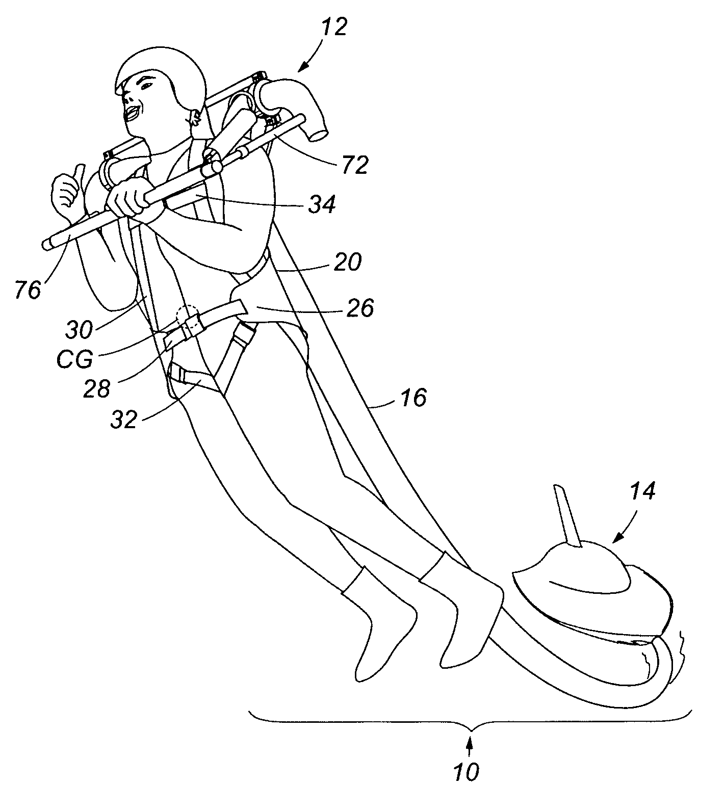
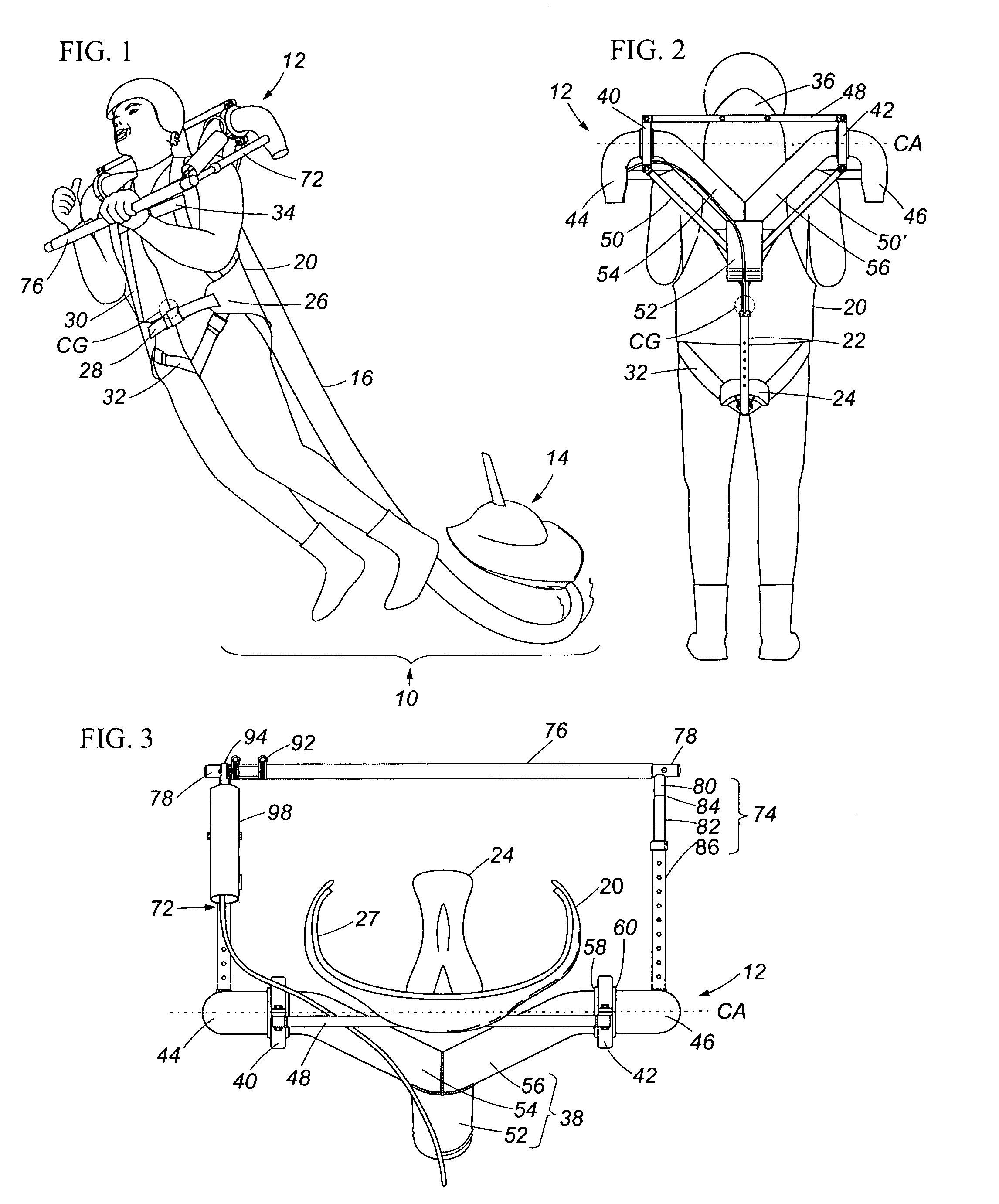
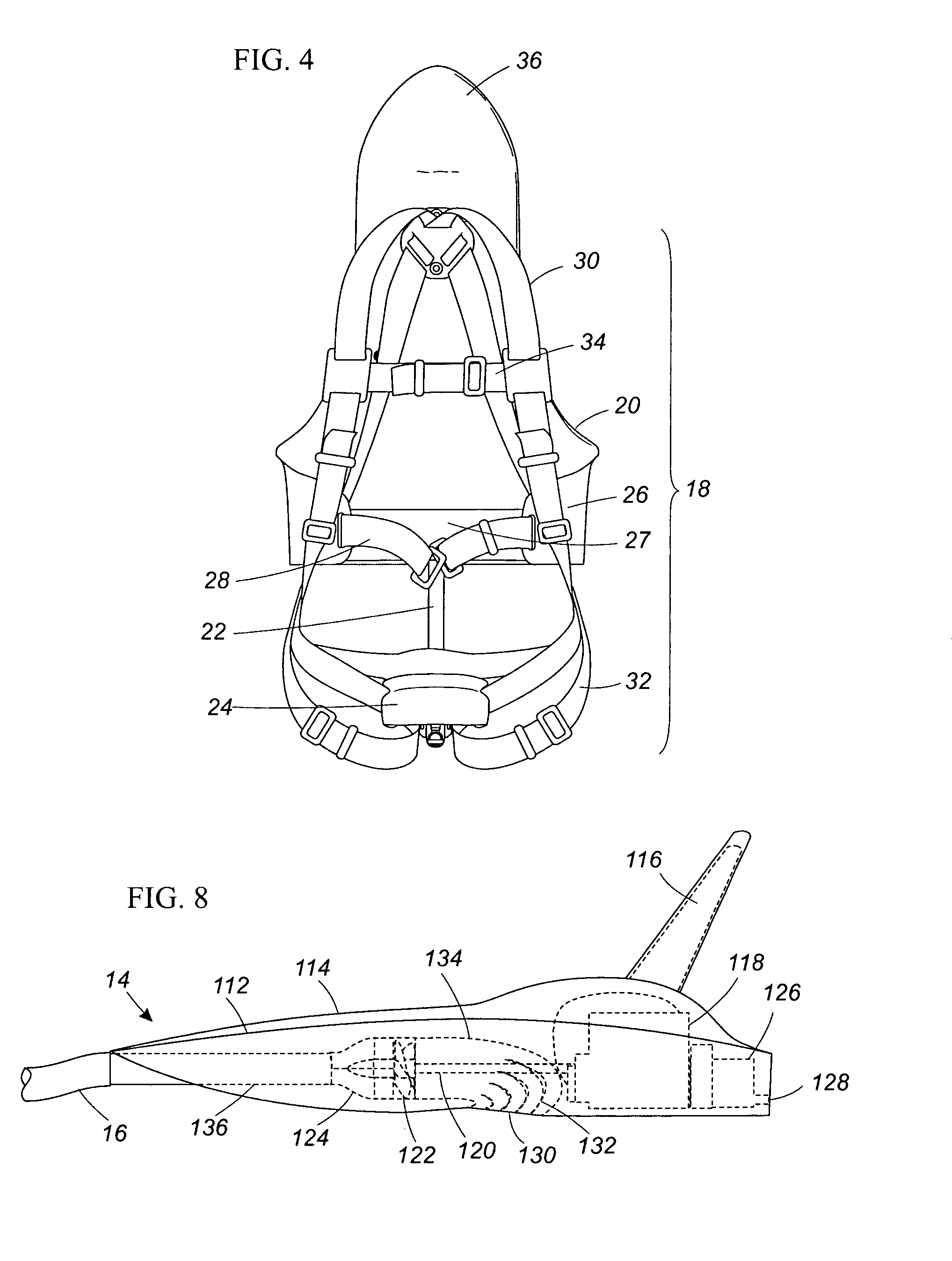
[0029]Now referring to FIGS. 1 through 4, an exemplary embodiment of the present invention provides a personal propulsion device 10 having a body unit 12, a base unit 14 capable of providing pressurized fluid flow, and a delivery conduit 16 in fluid communication with both the body unit 12 and the base unit 14.

[0030]The body unit 12 includes a body harness system 18 having a torso corset 20, a seat post 22 and a saddle 24. The torso corset 20 may have a modified barrel shape, contoured to provide firm support, protection and comfort for the torso, while further transmitting the lifting and gravity forces to an operator. While the torso corset 20 is preferably made of a generally rigid material such as fiberglass-reinforced plastic, the torso corset 20 may include flexible extension flaps 26 that wrap around the waist of an operator. An extension flap cushioning 27 may be attached to the extension flaps 26, thereby providing a band of foam-like material that cushions and supports the...


PUM


Abstract

The present invention provides a personal propulsion device including a body unit having a center of gravity, where the body unit includes a thrust assembly providing a main conduit in fluid communication with at least two thrust nozzles, with the thrust nozzles being located above the center of gravity of the body unit. The thrust nozzles are independently pivotable about a transverse axis located above the center of gravity, and may be independently controlled by a single common linkage. The present invention may further include a base unit having an engine and a pump, which provides pressurized fluid to the body unit through a delivery conduit in fluid communication with both the base unit and the thrust assembly.

Description

CROSS-REFERENCE TO RELATED APPLICATION[0001]This application is related to and claims priority to U.S. Provisional Patent Application Ser. No. 60 / 556,396, filed Mar. 26, 2004, entitled PERSONAL PROPULSION DEVICE, which application is related to U.S. Provisional Patent Application Ser. No. 60 / 581,438, filed Jun. 22, 2004, entitled PERSONAL PROPULSION DEVICE, the entirety of which is incorporated herein by reference.STATEMENT REGARDING FEDERALLY SPONSORED RESEARCH OR DEVELOPMENT[0002]n / aFIELD OF THE INVENTION[0003]The present invention relates to powered flight, more specifically, to a personal propulsion device.BACKGROUND OF THE INVENTION[0004]Personal flight has been an eternal dream and a recent reality. However, unlike birds, human beings have a low power-to-weight ratio, and personal flight has only been accomplished by developing machines using powerful engines and aerodynamic lifting surfaces, such as autogyro aircraft, fixed wing airplanes, and helicopters. Arguably, the close...

Claims


Application Information

Patent Timeline
Patent Type & Authority Patents(United States)
IPC IPC(8): B64C29/00B64C39/02B63C11/46
CPCA63B35/00B64C39/026B63H11/04B63H2011/006B63B34/15
Inventor LI, RAYMOND
Owner ZAPIP LLC
Learn More