
System and method to calculate round trip delay for real time protocol packet streams

a technology of real-time protocol and delay, applied in the field of system and method to calculate the time, can solve the problems of increasing the delay between the time, not addressing resource reservation, not ensuring the quality of service of real-time services, and not ensuring delivery or preventing out-of-order

Active Publication Date: 2007-08-14
VIAVI SOLUTIONS INC
View PDF3 Cites 60 Cited by
  • Summary
  • Abstract
  • Description
  • Claims
  • Application Information

AI Technical Summary

Benefits of technology

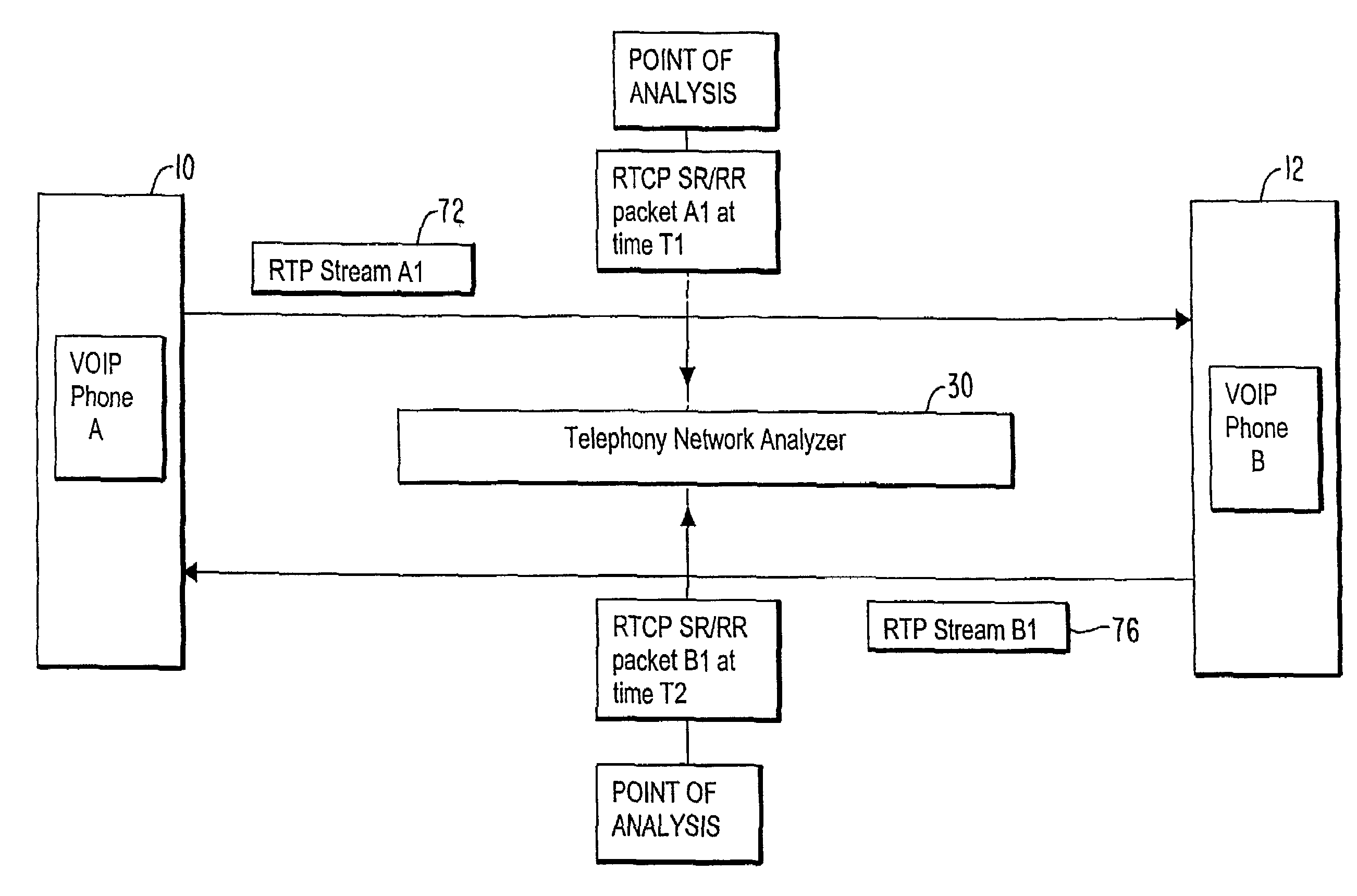
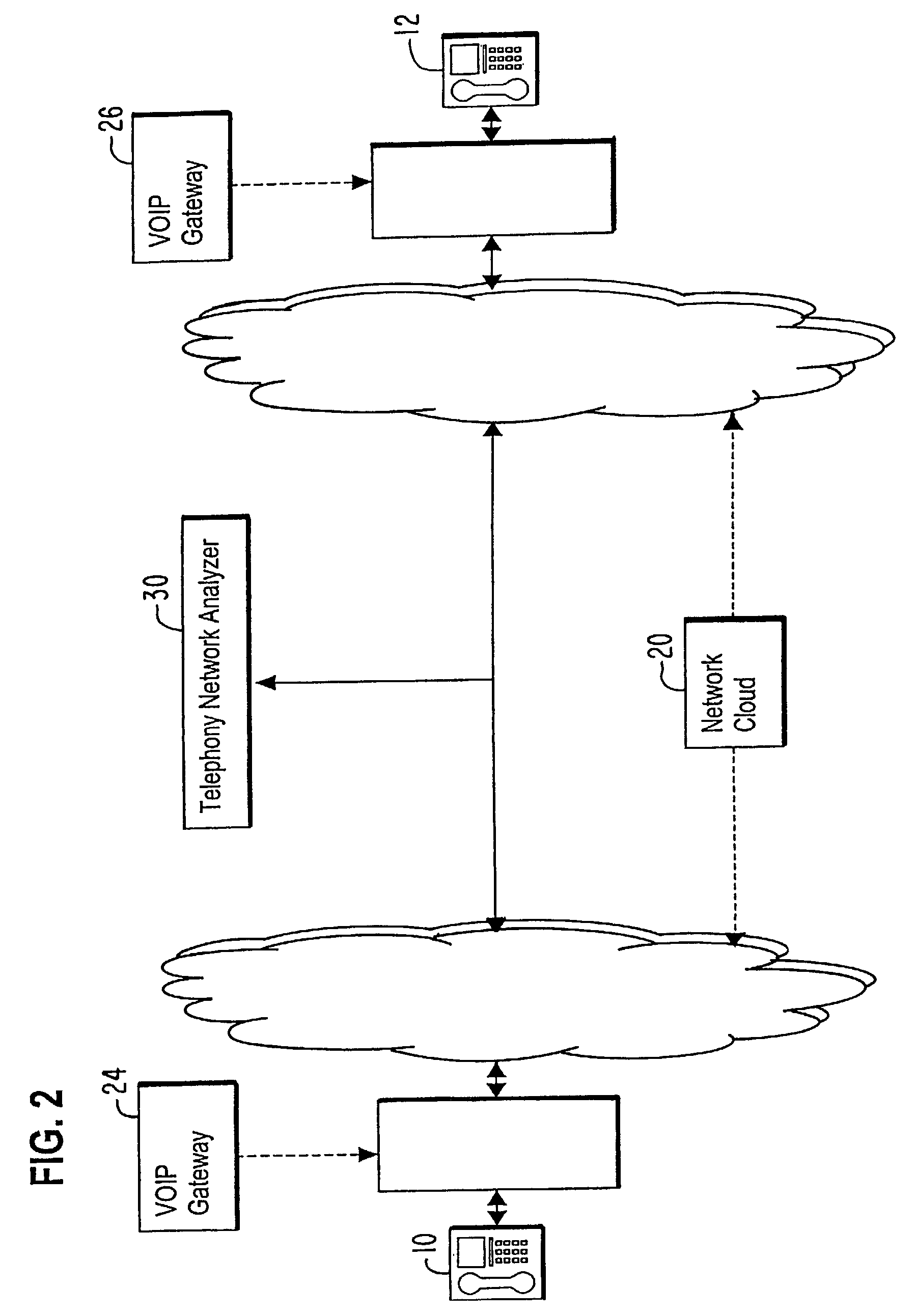
The present invention provides an apparatus and method for calculating the round-trip delay (RTD) between first and second endpoints within a network. This is useful for determining the time it takes for data to travel between the two points. The apparatus includes a network analyzer that measures the time it takes for data to be transmitted between the intermediate point and the endpoints, and the method involves adding the time stamps to calculate the round-trip delay. The technical effect of this invention is to provide a more accurate and reliable measure of data transmission time between points in a network, which can aid in the analysis and design of network infrastructure.

Problems solved by technology

The RTP stream does not address resource reservation and does not guarantee quality-of-service for real-time services.
However, the RTP stream itself does not provide any mechanism to ensure timely delivery or provide other quality-of-service guarantees, does not guarantee delivery or prevent out-of-order delivery, nor does the RTP stream assume that an underlying network is reliable and delivers packets in sequence.
An increase in the amount of delay between the time when a message signal is sent out and when the message is transmitted back is objectionable as this delay creates, for instance, echo of the message.
However, in this case, radio waves of the message are subjected to various microwave obstructions, such as buildings, thus the RTD inherently includes a delay resulting from reflection by such obstructions.
This type of delay degrades the accuracy of locating an exact position of a mobile phone and degrades message transmission in real time.

Method used


Image

  • System and method to calculate round trip delay for real time protocol packet streams
  • System and method to calculate round trip delay for real time protocol packet streams
  • System and method to calculate round trip delay for real time protocol packet streams

Examples


Embodiment Construction

[0016]Hereinafter, embodiments of the present invention will be described in detail with reference to the attached drawings. The present invention may, however, be embodied in many different forms and should not be construed as being limited to the embodiments set forth herein; rather, these embodiments are provided so that the present disclosure will be thorough and complete, and will fully convey the concept of the invention to those skilled in the art.

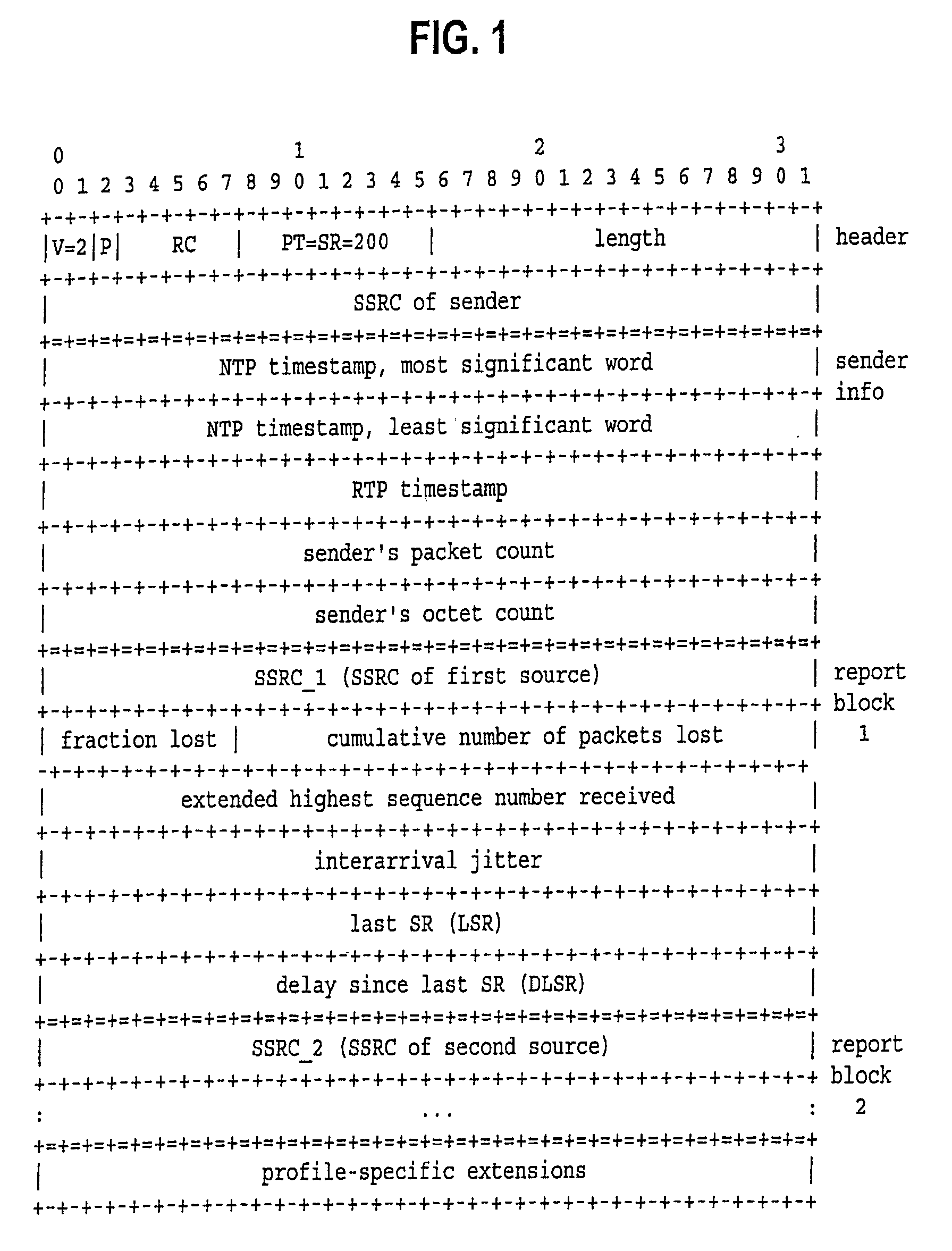
[0017]RTP has header fields that are either fixed or deterministically varying, with a certain format. These fields include fields for a sequence number, time stamp, synchronization source identifiers, and contributing source identifiers. The header fields can be extended with RTP header extension to provide new payload-format-independent functions that require additional information to be carried in an RTP data packet header. Additionally, RTCP packets have a packet format and header fields for control information. The RTCP header ...


PUM


Abstract

An apparatus and method calculate a round-trip delay (RTD) between first and second endpoints within a network, where an intermediate point is selected between the first and second endpoints within the network. A network analyzer determines a first data transmission time from the intermediate point to the first endpoint and back to the intermediate point, determines a second data transmission time from the intermediate point to the second endpoint and back to the intermediate point, and adds the first and second data transmission times to determine therefrom the round trip delay between the first and second endpoints within the network.

Description

BACKGROUND OF THE INVENTION[0001]A real-time protocol (RTP) provides end-to-end network transport functions suitable for applications transmitting real-time data, such as audio, video or simulation data, over multicast or unicast network services. An RTP stream includes RTP data packets, which includes encoded audio or video information, and a control protocol (RTCP control packets), which carry control information. The RTP stream does not address resource reservation and does not guarantee quality-of-service for real-time services. The data transport is augmented by the RTCP control packets to allow monitoring of the data delivery in a manner scalable to large multicast networks, and to provide minimal control and identification functionality.[0002]The RTP and RTCP data packets are designed to be independent of the underlying transport and network layers. However, the RTP stream itself does not provide any mechanism to ensure timely delivery or provide other quality-of-service guar...

Claims


Application Information

Patent Timeline
Patent Type & Authority Patents(United States)
IPC IPC(8): H04L12/26H04L12/56H04J3/06H04L7/00H04L12/64H04L69/40H04M7/00
CPCH04J3/0682H04L12/6418H04L43/0864H04L65/608H04L65/80H04L29/06027H04L41/5003H04L2012/6472H04L2012/6481H04M7/0006H04L65/65H04L65/1101
Inventor GROVENBURG, WILLIAM GRANT
Owner VIAVI SOLUTIONS INC
Learn More