Method and apparatus for automatically optimizing optical contrast in automated equipment
a technology of automatic optimization and optical contrast, applied in the field of electronic vision systems, can solve the problems of inability to accurately identify or locate a desired feature of a part, difficulty in obtaining adequate visual contrast, processing inconvenience, etc., and achieve the effect of optimizing the contrast of an attribute, optimizing the illuminating light color and intensity, and compensating for variations in surface texture, reflectivity, color or other appearance features
- Summary
- Abstract
- Description
- Claims
- Application Information
AI Technical Summary
Benefits of technology
Problems solved by technology
Method used
Image

Examples
second embodiment
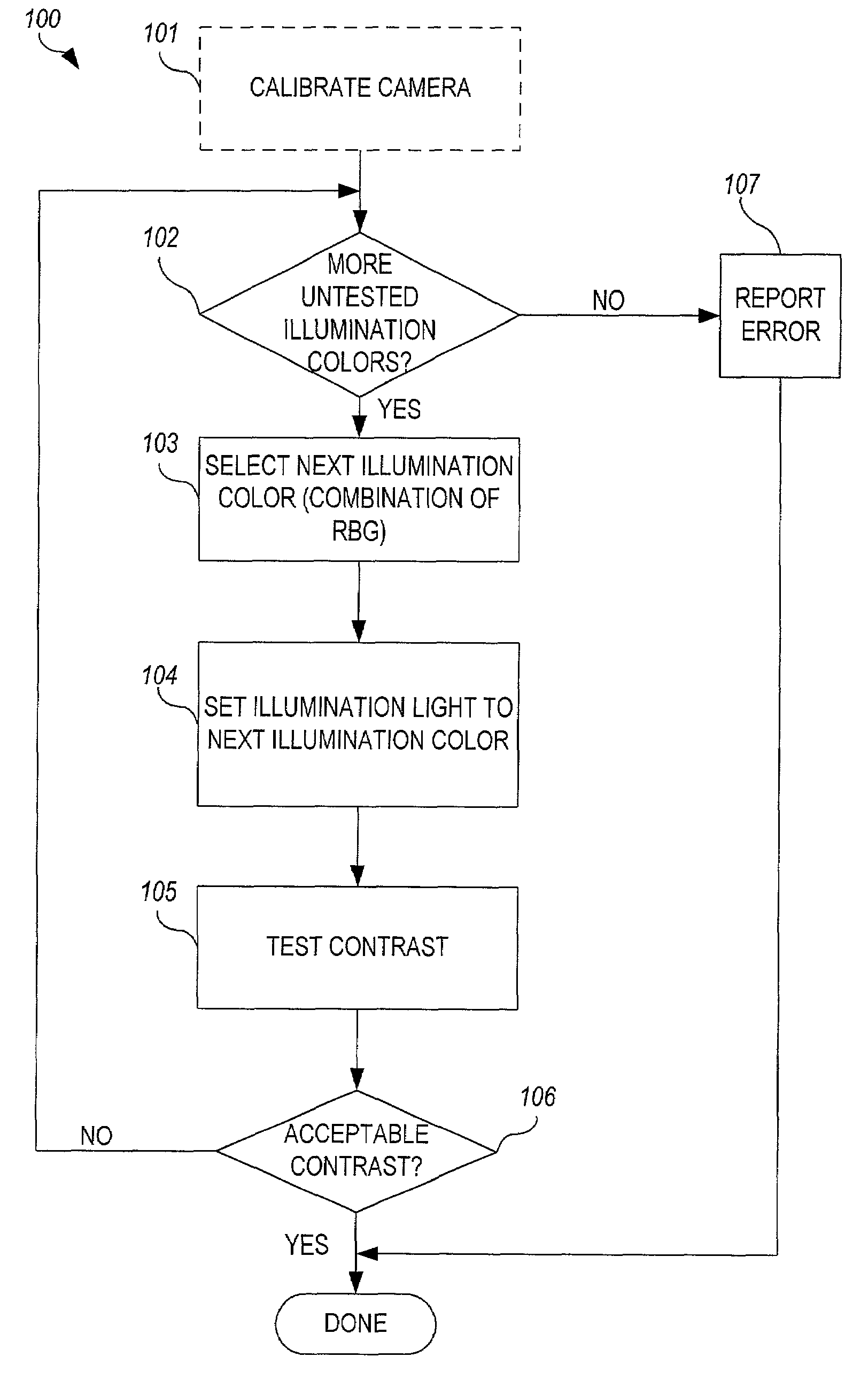
[0055]FIG. 9B is a flowchart illustrating a method 110 for optimizing the contrast and illumination of the LEDs of a vision system. In this embodiment, the camera is again calibrated 111. Then, a first illumination color is selected 112 / 113. The current in each of the red, green, and blue LEDs is independently adjusted 114 to generate the selected illumination color. Feedback from the camera 20 is used to test 115 the contrast level using illumination light having the selected illumination color. The contrast level associated with the selected illumination color is recorded 116. A determination is then made 112 as to whether any untested illumination colors remain to be tested. If so, steps 113 through 116 are repeated until a determination is made 112 (following each occurrence of step 116) that no untested illumination colors remain to be tested. Once the contrast level has been obtained for all available illumination colors, the contrast levels for each available illumination col...
third embodiment
[0056]FIG. 9C is a flowchart illustrating a method 120 for optimizing the contrast and illumination of the LEDs of a vision system. In this embodiment, the camera is again calibrated 121. Then, a first coarse illumination color is selected 122 / 123. The current in each of the red, green, and blue LEDs is independently adjusted 124 to generate the selected coarse illumination color. Feedback from the camera 20 is used to measure 125 the contrast level using illumination light having the selected coarse illumination color. The contrast level associated with the selected coarse illumination color is recorded 126. A determination is then made 122 as to whether any untested coarse illumination colors remain to be tested. If so, steps 123 through 126 are repeated until a determination is made 122 (following each occurrence of step 126) that no untested coarse illumination colors remain to be tested. The coarse illumination color having the “best” contrast level from the recorded coarse con...
PUM
 Abstract
Description
Claims
Application Information
 - R&D
- Intellectual Property
- Life Sciences
- Materials
- Tech Scout
- Unparalleled Data Quality
- Higher Quality Content
- 60% Fewer Hallucinations
Browse by: Latest US Patents, China's latest patents, Technical Efficacy Thesaurus, Application Domain, Technology Topic, Popular Technical Reports.
© 2025 PatSnap. All rights reserved.Legal|Privacy policy|Modern Slavery Act Transparency Statement|Sitemap|About US| Contact US: help@patsnap.com