
Method and system for combined standing pilot safety and temperature setting

a standing pilot and temperature setting technology, applied in the field of control systems, can solve the problems of inability to operate, system overrun, and difficulty in using external power sources in certain cases, and achieve the effects of reducing the number of pilots, and reducing the safety of standing pilots

Active Publication Date: 2007-08-07
ADEMCO INC
View PDF35 Cites 62 Cited by
  • Summary
  • Abstract
  • Description
  • Claims
  • Application Information

AI Technical Summary

Benefits of technology

This solution provides a reliable, accurate, and cost-effective control system for gas-powered appliances that operates independently of external power sources, improving functionality and reducing costs by utilizing thermal energy to power the control circuit.

Problems solved by technology

In this respect, appliances with external power sources may be difficult to use in certain situations due to availability and / or proximity of a suitable power source.
Additionally, such systems typically do not function in the event of a power outage, which is undesirable.
While a thermo-mechanical back-up control system may be included in such an appliance, that approach may be overly redundant and cost prohibitive in a commercial application.
Such thermo-mechanical controls are typically inaccurate due to machining tolerances, mechanical hysteresis and the use of only a single temperature sensing location due to the impracticability of multiple sensor configurations.
Further, gas-powered appliances with a standing ignition might also suffer certain disadvantages from having separate operating means for system start-up and temperature selection.

Method used


Image

  • Method and system for combined standing pilot safety and temperature setting
  • Method and system for combined standing pilot safety and temperature setting
  • Method and system for combined standing pilot safety and temperature setting

Examples


Embodiment Construction

1. Exemplary Architecture

[0024]It should be appreciated that while exemplary embodiments are described with particular reference to an appliance control system for controlling a gas-fired water heating device, the present invention is contemplated for use with other appliances, including those which generate heat using electricity, a heat pump, oil, and the like. In addition, the gas-fired heating appliance may use a variety of suitable ignition systems, including standing pilot ignition, spark ignition, and hot surface ignition.

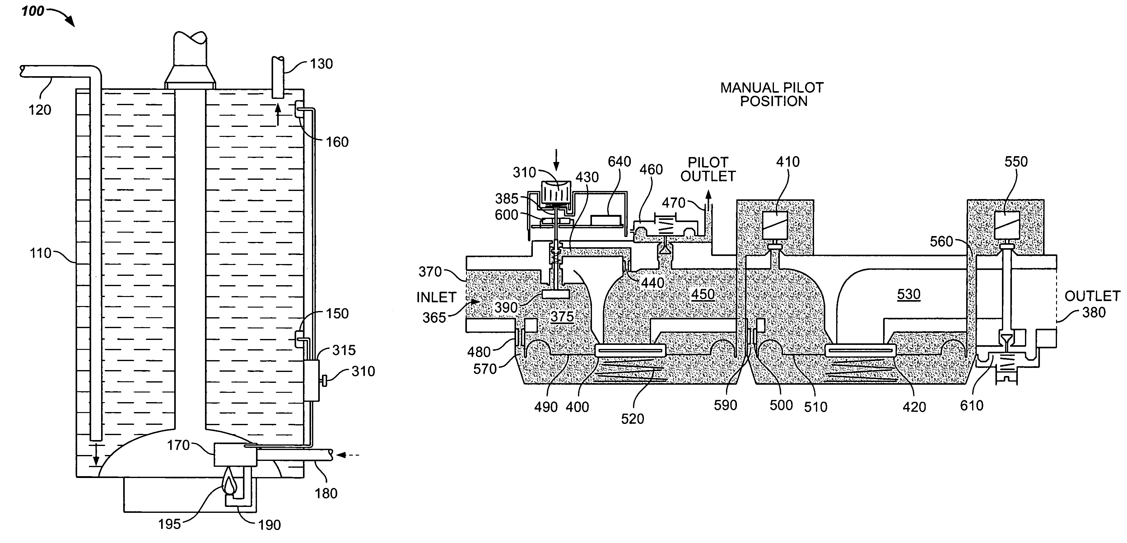
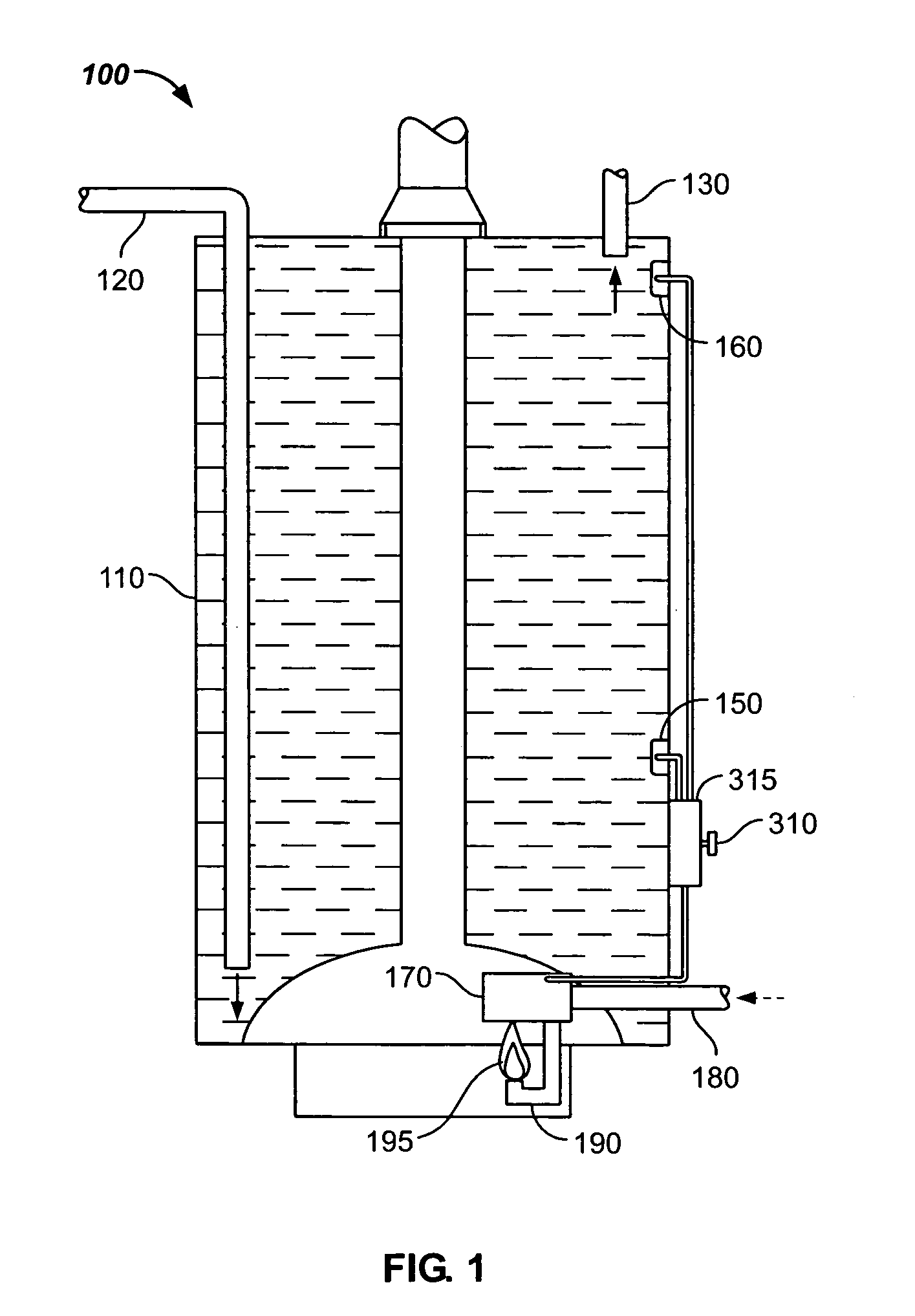
[0025]Referring now to the drawings, which illustrate exemplary embodiments only and are not for purposes of limiting the claims, FIG. 1 depicts an exemplary embodiment of a water heating device (“water heater”) 100. Water heater 100 might include a storage tank 110 for storing water that has been, or is to be heated. Water heater 100 might also include a water supply feed pipe (typically cold water) 120, and a hot water exit pipe 130. Additionally, water he...


PUM


Abstract

The method and apparatus provides a controller (which might comprise a microprocessor) that can control gas flow to a pilot burner in fluid communication with a manual pilot valve and an automatic pilot valve. The exemplary embodiments can comprise a selectable input device that can open the manual pilot valve to allow gas flow to the pilot burner. A pilot flame can then heat one or more thermal detection devices in thermal communication with the pilot burner, wherein the one or more thermal detection devices can output a variable voltage potential to the controller. The controller can then open the automatic pilot valve to maintain gas flow to the pilot burner after the manual pilot valve has been closed. In an exemplary embodiment, the only voltage potential used to power the controller is supplied by the one or more thermal detection devices.

Description

BACKGROUND[0001]1. Field of the Invention[0002]The present invention relates generally to a controller, and more particularly relates to a control system for controlling an appliance, such as a gas-fired heating device.[0003]2. Description of the Related Art[0004]Gas-powered appliances typically have some control system included for controlling the operation of the appliance. In this context, a gas-powered appliance may be a water heater, a fireplace insert, or a furnace, for example. Also in this context, “gas-powered” typically means that natural gas or liquid propane gas is used as a primary fuel source. Current control systems used in gas-powered appliances are typically powered by a source external to the appliance, or take the form of a thermo-mechanical system, of which both approaches have certain disadvantages.[0005]In this respect, appliances with external power sources may be difficult to use in certain situations due to availability and / or proximity of a suitable power s...

Claims


Application Information

Patent Timeline
Patent Type & Authority Patents(United States)
IPC IPC(8): F23N1/00F23N5/00F23N5/14G05D7/06
CPCF23N1/002F23N5/00F23N5/14G05D7/0647Y10T137/1407Y10T137/1516Y10T137/7782
Inventor MUNSTERHUIS, SYBRANDUS B. V.
Owner ADEMCO INC
Learn More