System and method for recovering geothermal energy and for converting recovered geothermal energy into useful power

Inactive Publication Date: 2007-08-07
BOND WANDA +1
View PDF8 Cites 31 Cited by
  • Summary
  • Abstract
  • Description
  • Claims
  • Application Information

AI Technical Summary

Benefits of technology

[0006]The present invention is directed to system for recovering geothermal energy and converting it to useful power. The system comprises an energy conversion station installed in a cavity below the earth's surface. The energy conversion station has an inlet and an outlet. The system further comprises a heat exchange conduit system. The conduit system includes at least one feed conduit adapted to carry a heat exchange fluid from an entry level at or near the earth's surface down through

Problems solved by technology

If they can be tapped efficiently, our geothermal resources represent a practically inexhaustible source of non-fossil fuel.
Prior attempts to exploit geothermal energy have encountered various problems.
Most of the problems could have been anticipated from the nature of the unstable rocks where the projects have been located.
It is these conditions which foretell an unsatisfactory outcome.
Fractured formations release hydrogen sulfide and other undesirable gases, which should not be released into the atmosphere and which generate an unpleasant odor for miles around the site.
Steam produced from water passing through these fractured formations may be highly mineralized and corrosive on turbines and generators.
A large portion of the energy from the coal or gas used to heat the water is lost as exhaust up the smoke stack.
The big losses of energy occur when the cold water becomes high pressure steam.
In conventional generator systems, more than half the energy is being wasted.
Coal is the most cost effective system of electrical generation in use today, but it produces a high degree of pollution.

Method used


Image

  • System and method for recovering geothermal energy and for converting recovered geothermal energy into useful power
  • System and method for recovering geothermal energy and for converting recovered geothermal energy into useful power
  • System and method for recovering geothermal energy and for converting recovered geothermal energy into useful power

Examples


Embodiment Construction

[0016]Our earth is a nearly spherical body with an equatorial radius of about 4,000 miles. If the Earth were reduced to a table top globe only 20 inches in diameter, the portion that man has physically explored through the deepest mines and boreholes would be a mere skin, only about 0.04 inch thick. However, through geophysical calculations, based on sound wave velocities and propagation theories, the geologic structure of the earth's interior has been modeled.

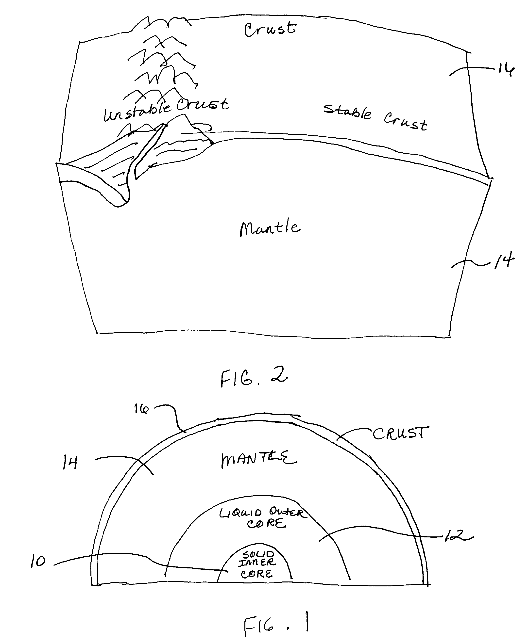
[0017]As illustrated in FIG. 1, the Earth has a solid inner ball or core 10 of nearly pure iron with a diameter of about 1500 miles and an unknown temperature. The propagation of sound waves indicates the center core is a solid at extreme pressures.

[0018]A fluid outer core 12 composed of a liquid iron alloy surrounds the core. The thickness of the fluid outer core is about 1300 miles. The temperature of the middle of the outer core must be greater than 9,600 degrees Fahrenheit for the iron to be molten at a pressure of 250 gig...


PUM


Abstract

Recovery and conversion of geothermal energy from geologically stable, hot, dry rock is disclosed. Deep boreholes are drilled to form a system of feed and return conduits in the non-porous formation. Fluid is passed through the conduits where heat energy is transferred to the moving fluid. The return conduit brings the hot fluid to an energy conversion station located underground where the thermal energy is converted into electrical energy. Power from the generator and warm water are supplied to the community for use. To form the deep boreholes, a series of large diameter boreholes is drilled, and the rig is moved down at intervals until the environment becomes intolerable. At that depth, a final borehole is drilled to reach the optimum temperature level. The system of this invention taps an unlimited source of energy in this country and accomplishes this in a manner that is both cost efficient and environmentally friendly.

Description

FIELD OF THE INVENTION[0001]The present invention relates generally to systems and methods for recovering geothermal energy found deep beneath the earth's surface and converting this thermal energy into usable power, and to methods for deep drilling to reach these reserves in stable subterranean formations.BACKGROUND OF THE INVENTION[0002]The potential for generating energy using the heat energy found within the earth, sometimes called “heat mining,” has been the subject of much investigation over many years. If they can be tapped efficiently, our geothermal resources represent a practically inexhaustible source of non-fossil fuel.[0003]Prior attempts to exploit geothermal energy have encountered various problems. Most of the problems could have been anticipated from the nature of the unstable rocks where the projects have been located. Some have attempted to recover geothermal energy from locations where unusually high temperatures are found relatively close to the surface. These g...

Claims


Application Information

Patent Timeline
IPC IPC(8): F03G7/00
CPCF03G7/04F24J3/081Y02E10/12F24T10/10Y02E10/10
Inventor BOND, LESLEY O.
Owner BOND WANDA
Why Eureka
Try Eureka