High-resolution fiber laser sensor
a fiber laser and high-resolution technology, applied in the direction of lasers, converting sensor output, instruments, etc., can solve the problems of small frequency widening of measurement signals, inaccuracy of measurement signals, and problems in signal spectra interpretation, so as to improve resolution and reduce the line width of detected signals.
- Summary
- Abstract
- Description
- Claims
- Application Information
AI Technical Summary
Benefits of technology
Problems solved by technology
Method used
Image

Examples
Embodiment Construction
[0010]It is, therefore, the object of the invention to create a fiber laser sensor of the type initially mentioned and a corresponding measuring method which do not have the abovementioned disadvantages. In particular, it is intended to achieve a high measuring accuracy, cost-effective production and versatile applicability.
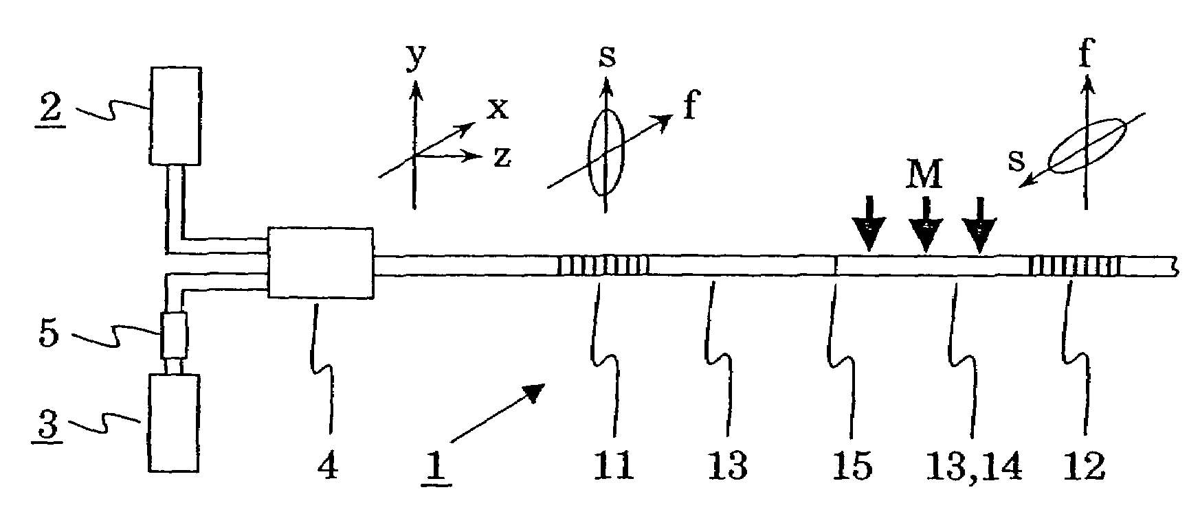
[0011]In the sensor according to the invention, the two end reflectors are detuned with respect to one another. Because the fiber laser sensor comprises the means for mode coupling and at least the first end reflector is birefringent, the extensive degeneracy of the PMB signals for every order can be cancelled. The frequency separation between adjacent longitudinal modes in a first one of the two orthogonal optical states is greater than the frequency separation between adjacent longitudinal modes in the second one of the two orthogonal optical states. The degeneracy of the PMB signals of a given order can be cancelled to such an extent that these PMB signals do ...
PUM
| Property | Measurement | Unit |
|---|---|---|
| frequency | aaaaa | aaaaa |
| cavity length | aaaaa | aaaaa |
| frequency | aaaaa | aaaaa |
Abstract
Description
Claims
Application Information
 - R&D
- Intellectual Property
- Life Sciences
- Materials
- Tech Scout
- Unparalleled Data Quality
- Higher Quality Content
- 60% Fewer Hallucinations
Browse by: Latest US Patents, China's latest patents, Technical Efficacy Thesaurus, Application Domain, Technology Topic, Popular Technical Reports.
© 2025 PatSnap. All rights reserved.Legal|Privacy policy|Modern Slavery Act Transparency Statement|Sitemap|About US| Contact US: help@patsnap.com